NOTICE
Risk of improper power-supply connection. Can cause equipment damage and loss of warranty
coverage.
Prior to connecting any equipment to a main or alternate power source (for example: back-up
generator systems) for start-up, commissioning, testing, or normal operation, ensure that these
sources are correctly adjusted to the nameplate voltage and frequency of all equipment to be
connected. In general, power-source voltages should be stabilized and regulated to within
±10% of the load nameplate nominal voltage. Also, ensure that no three-phase sources are
single-phased at any time.
NOTICE
Risk of improper electrical connection of three-phase input power. Can cause backward
compressor rotation and unit damage. Service technicians should use a gauge set on the
system during the initial start up to verify that the three-phase power is connected properly.
The EC fans are not a reliable indicator of proper connection. The blowers will rotate the same
direction, regardless of the three-phase power input. Three-phase power must be connected
to the unit line voltage terminals in the proper sequence so that the compressors rotate in the
proper direction. Incoming power must be properly phased to prevent compressors from
running backward. We recommend checking the unit’s phasing with proper instrumentation to
ensure that power connections were made correctly. We also recommend verifying discharge
and suction pressures during start up to ensure that the compressors are running in the
correct direction.
NOTICE
Risk of improper electrical supply connection. Can cause equipment damage. See transformer
label for primary tap connections. Installer will need to change transformer primary taps if
applied unit voltage is other than pre-wired tap voltage.
NOTE: Seal openings around piping and electrical connection to prevent air leakage. Failure to do so
could reduce the unit’s cooling performance.
The electrical and unit-to-unit connections are described in the submittal documents included in the
Submittal Drawings on page93.
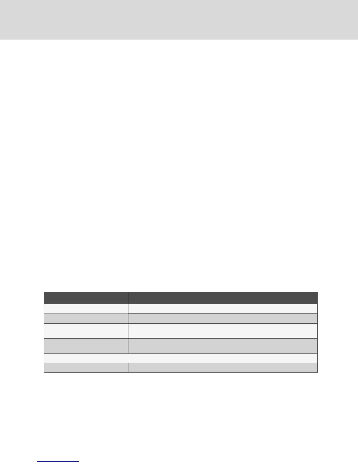
The following tables list the relevant documents by number and title.
Document Number Title
DPN004387 Electrical Field Connections, Upflow & Downflow, DA050, DA080, and DA085 Models
DPN004388 Electrical Field Connections, Downflow Models, DA125, DA150, and DA165
DPN003284
CANbus cable connections between indoor unit, 1 Liebert® MCcondenser and optional
Liebert® EconoPhase pump
DPN002361
CANbus cable connections between indoor unit, 2 Liebert® MCcondensers and optional
Liebert® EconoPhase pump
Unit-to-Unit Networking
DPN004351 Liebert® iCOM Unit-to-unit Network Connections
Table 6.1 Electrical Field-connection Drawings
Vertiv | Liebert® DSE™ Installer/User Guide
44