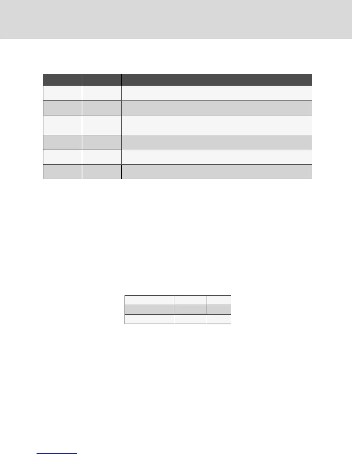
EC-fan Fault Conditions
Fault Condition Reset Trigger Description
Phase Failure Automatic
One phase is missing. In this case the motor will come to a stop and then automatically restart
when allphases are present.
Locked/Blocked
Rotor
Automatic
The rotor is blocked. Once the locking mechanism has been removed, the motor will
automatically restart.
Hall Effect
Sensor Error
Manual
(Mains/Software)
The Hall Effect Sensor is used to monitor fan speed. If there is a hall sensor communication
failure with the electronics, the motor will stop. In this case there has to be amanual restart
(either with the mains power or software).
Motor Over
Temperature
Manual
(Mains/Software)
The motor will stop in the event there is a motor over temperature condition. In this case
there has to be a manual restart (either with the mains power or software).
Electronics Over
Temperature
Manual
(Mains/Software)
The motor will stop in the event there is an electronics over temperature condition. In this
case there has to be amanual restart (either with the mains power or software).
Line
Under-Voltage
Automatic
Once the line voltage returns within permitted operating range, the fan will automatically
restart.
Table 10.2 EC-fan Fault Conditions
EC-fan High-voltage Tests
1. Check Fuses. If fuses are okay, perform the following:
• Check all connections.
• Make sure connections are on the wire strand and not on the wire insulation.
• Cycle Power. Disconnect mains voltage to power down the motor and then re-apply
power.
• Check mains voltage at each phase (phase to ground) at the KL1 connector.
Confirm phase failure not present.
• Check that the voltage is within the acceptable voltage range at the KL1
connector. Confirm line under-voltage is not present.
2. Check Fuses. If fuses are blown, perform the following:
• Check resistances across the phases at the KL1 connector and note them in the
following table..
NOTE: Power wires must be removed from the motor for resistance test.
L1 - L2 Ohm
L2 - L3 Ohm
L1 - L3 Ohm
• Resistances should be similar for all 3 readings.
Vertiv | Liebert® DSE™ Installer/User Guide
58