NOTICE
Risk of improper disassembly. Can cause equipment damage.
Disassembling this unit requires substantial work, including reclaiming refrigerant and
charging the unit, cutting and brazing refrigerant lines, cutting and brazing water lines,
disconnecting and reconnecting electrical lines and moving heavy, bulky equipment. One
member of the crew disassembling the unit must be qualified in wiring, brazing and
refrigeration.
Improperly disassembling or reassembling the DSE may affect warranty.
The disassembly dimensions and details are described in the submittal documents included in the
Submittal Drawings on page93.
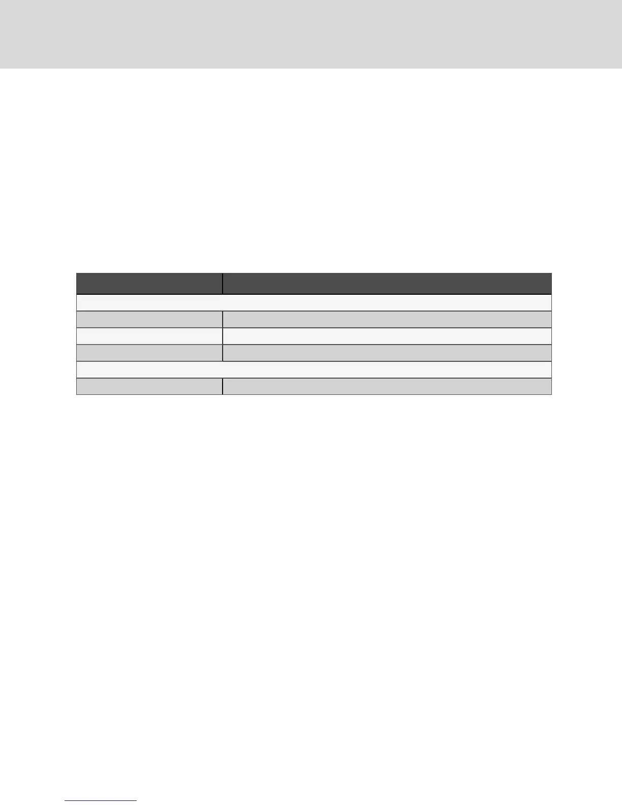
The following table lists the relevant documents by number and title.
Document Number Title
Downflow Units
DPN003532 Disassembly, DA050
DPN003140 Disassembly, DA080 and DA085
DPN003178 Disassembly, DA125, DA150 and DA165
Upflow Units
DPN003166 Disassembly, DA080U and DA085U
Table B.1 Disassembly Dimension Drawings
B.1 Required Equipment
• Piano jacks
• Stepladder
• Refrigeration tools
B.2 Downflow DA050, DA080 and DA085 Disassembly
1. Remove the unit from its shipping skid before beginning.
2. Remove all panels except the top front accent.
3. Remove all filters. This allows access to the screws for metal plate blocking off the top coil and
removal of the filter plate.
All wires are hot-stamped and all circuit board connectors are lettered to ease connection.
Some cable ties must be cut and replaced. Refer to the unit’s wiring schematic on the unit’s
dead-front panel for details.
NOTICE
Risk of improper handling and storage. Can cause equipment damage.
Do not lay the compressor section on its side. It must remain upright. The coil section also must
remain upright.
4. Label the three quick-connect plugs from the compressor compartment and disconnect them.
5. Disconnect the two CAN connections and cut the wire ties going to the EEV boxes in the
bottom of the compressor section.
6. Disconnect the compressor wire harness, including the crankcase heater wires, if present, from
the contactor in the electric box.
7. Pull the conduit and wires into the compressor compartment.
8. Disconnect the fan motor wire harness from the bottom of the contactor in the electric box.
9. Pull the conduit and wires into the bottom section of the DSE.
10. Reheat—Optional Component
Vertiv | Liebert® DSE™ Installer/User Guide
84