Vertiv
™
| Liebert® EXL
™
S1 Touchscreen Control User Manual | 11
Figure 7 Mimic display, normal operation, system view
2.3.1 UNIT STATUS Pane Components
The UNIT STATUS pane is identical for all PIN access levels (see Figure 8), if PIN’s are required.
Observers will not have the edit icon (pencil). In the default graphic view, the UNIT STATUS pane
shows:
• Status Gauge—Connected load shown in kW and as a percentage of capacity; input, output and bypass
voltage for each phase (default data may be changed; see 4.1 - Viewing UPS Data with the Status Gauge).
• Load Detail Icon
•Input Detail Icon
• Bypass Detail Icon
• Battery Detail Icon
The detail icon for Environmental may be added to the UNIT STATUS pane if there is space.
Touching any of the detail icons reveals additional data about that selection in the opposite pane.
The data pane may be closed by touching the Close button or by touching any detail icon. The
read-only information is available to all access levels (see Figures 9 through 13).
NOTE
If the Status Gauge is showing, no more than four detail icons will be visible. Removing the Status
Gauge permits showing all five detail icons. The view may be customized to show fewer than four.
Touching the arrowhead reveals the
Green outline
indicates
communication is
active and operating
normally.
White outline indicates
no communication
occurring.
Yellow indicates the
unit is communicating
but in a warning state.
System view is
obtained by touching
SYSTEM in the
default mimic view.
To return to default
view, touch Unit 1 or
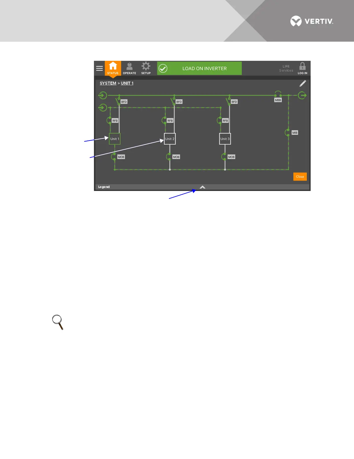 Loading...