Vertiv | Liebert® GXT5™ | Installer/User Guide 27
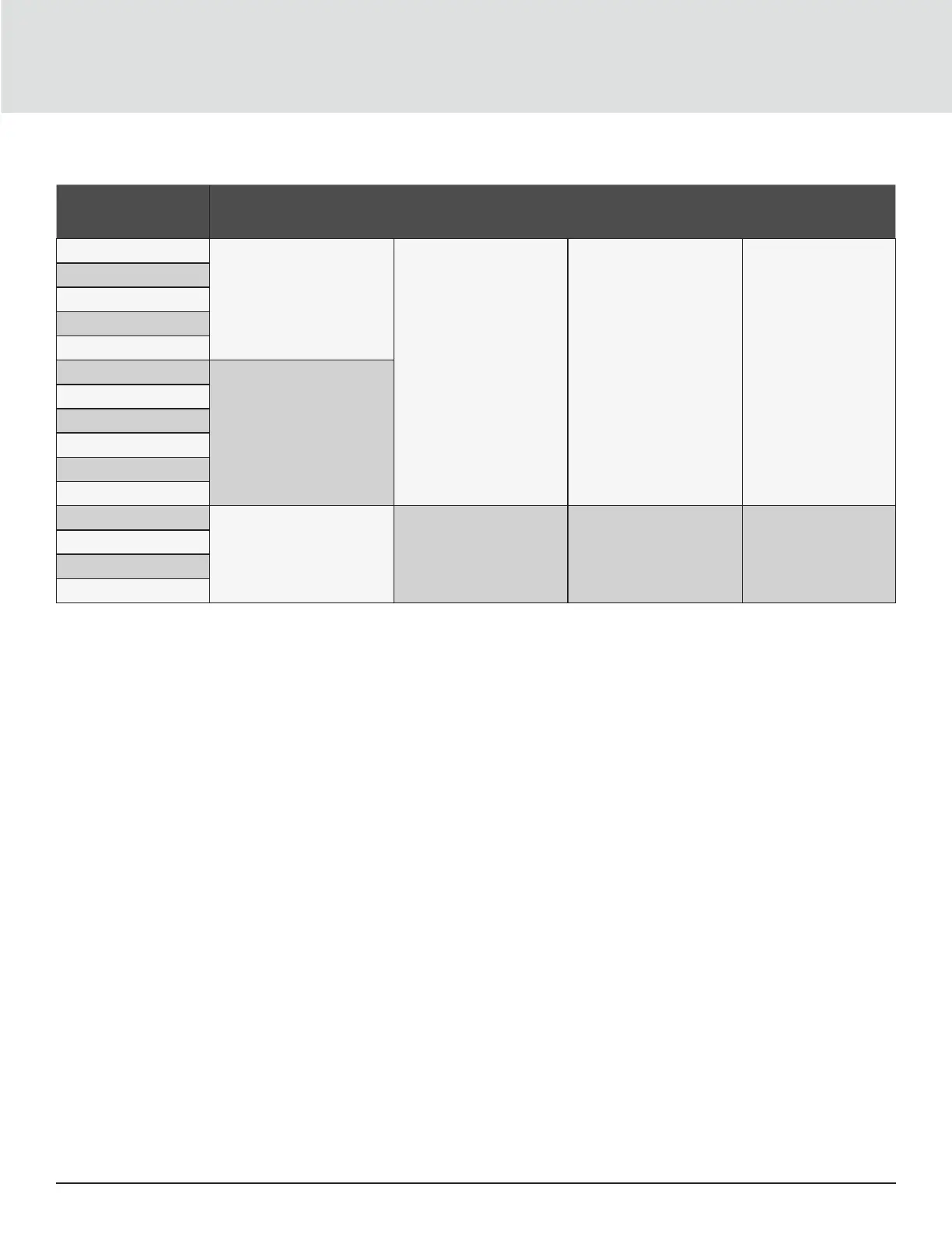
Table 2-3 Terminal-block electrical specications
UPS MODEL
RECOMMENDED (MAXIMUM)
EXTERNAL OVER-CURRENT
PROTECTION
RECOMMENDED WIRE
SIZE (INCLUDING GROUND
WIRE) (75°C COPPER WIRE)
MAXIMUM WIRE SIZE
ACCEPTED BY TERMINAL
BLOCK
TERMINAL
TIGHTENING TORQUE
GXT5-5000IRT5UXLN
60 A
10 mm
2
(7 AWG) 16 mm
2
(6 AWG) 20 in.-lb (2.26 Nm)
GXT5-5000IRT5UXLE
GXT5-5000HVRT5UXLN
GXT5-6000IRT5UXLN
GXT5-6000IRT5UXLE
GXT5-8000IRT5UXLN
70A
GXT5-8000IRT5UXLE
GXT5-8000HVRTUXLN
GXT5-10KIRT5UXLN
GXT5-10KIRT5UXLE
GXT5-10KHVRT5UXLN
GXT5-16KIRT9UXLN
1-phase: 160 A
3-phase: 50 A
35 mm² (1 AWG) 53.5 mm² (1/0 AWG) 110 in.-lb (12.4 Nm)
GXT5-16KIRT9UXLE
GXT5-20KIRT9UXLN
GXT5-20KIRT9UXLE
To make the terminal-block connections:
1. Loosen the screws from the cable-entry/conduit-box cover, and pull the cables through the cable-entry hole/
knockout leaving some slack for connection.
NOTE: Some UPS models have both a cable-entry hole and knockouts. For EU users, we recommend that you use
the cable-entry hole. However, if you use the knockouts, you must use a suitable cable and gland or risk electric
shock. For North American users, we recommend using the knockouts, and you must install input and output
wiring in separate conduit.
2. Referring to the appropriate terminal-block connection instructions, connect the cables to the corresponding
input/output terminals and use a torque wrench to turn the screw clockwise until tightened as specied in
Table 2-3 above.
• Connecting to Terminal Blocks on 5-kVA and 6-kVA models on the facing page
• Connecting to Terminal Blocks on 8-kVA and 10-kVA models on the facing page
• Connecting to Terminal Blocks on 16-kVA and 20-kVA models on page 30
3. Re-install the cable-entry/conduit-box cover, and tighten the screws.
 Loading...