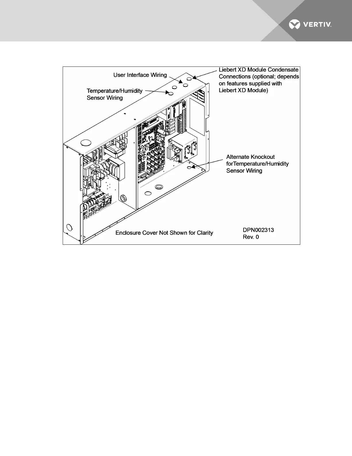
Figure 3.17 Electrical enclosure knockout locations for Extra Low Voltage connections
Field Connections—All Units
• Place Sensor A in the higher-temperature portion of the cold aisle where the Liebert XD
modules are located. Alternatively, it may be placed on the return air side of the primary air
mover (e.g., Liebert DS
™
) in the room if it represents the conditions where all the Liebert XD
cooling modules are located. Do not install the sensor where ambient air might cause false
readings, for example, near unsealed doors, windows and similar areas.
1. Unpack the two remote temperature/humidity sensors and cables.
One sensor is labeled Sensor A and the other, Sensor B. The sensor cables are interchangeable;
each bears labels indicating Sensor End and Unit End.
2. Connect the Sensor End of one of the supplied sensor cables to P66 on Sensor A (see Figure
3.16 on page29).
3. Connect the Unit End of the sensor cable to P4 on the CAN Isolator inside the Liebert XDC (see
Figure 3.16 on page29). Secure the terminal plug on the cable shield to the into the terminal
plug adjacent to P2 (see Figure 3.16 on page29).
4. Connect the Sensor End of the second sensor cable to P66 on Sensor B (see Figure 3.16 on
page29).
5. Connect the Unit End of the cable to P4 on the CAN Isolator inside the Liebert XDC (see Figure
3.16 on page29). Secure the terminal plug on the cable shield to the terminal plug adjacent to
P4 (see Figure 3.16 on page29).
Vertiv | Liebert® XDC™ User Manual | 31