5. Turn indicator control device
6. Turn indicator switch
7. Turn indicator bulbs (12V - 10W)
WARNING
ALL CONTINUITY TESTS MUST BE CARRIED OUT WITH THE CORRESPONDING CONNECTORS
DISCONNECTED.
1) Check that bulbs operate properly.
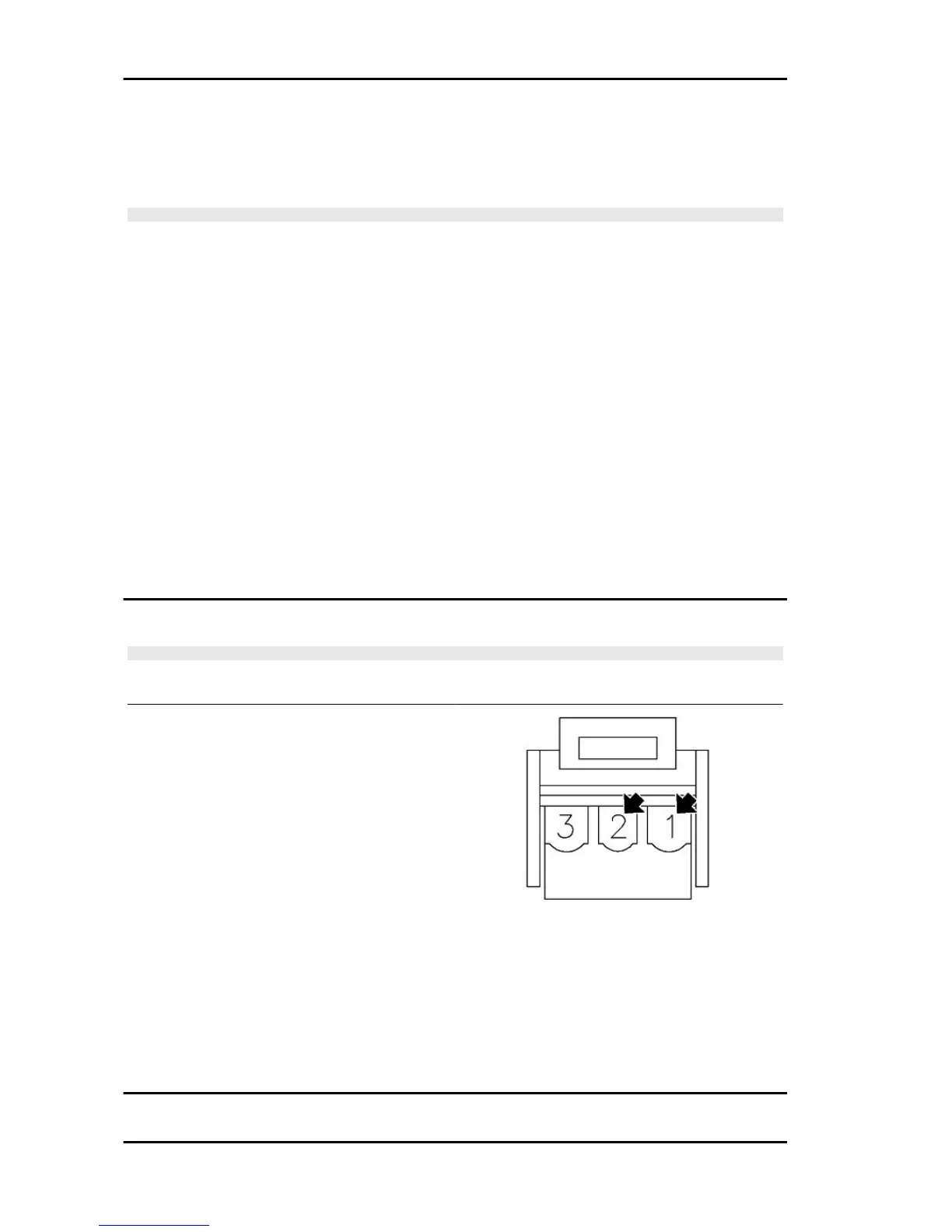
2) Check fuses No. 1 and 3.
3) Check key switch contacts.
4) With the key switch set to «ON», check if there is voltage between the Blue-Black cable of the turn
indicators switch and the ground connection. If there is not, check the cable harnesses and the con-
nections of the turn indicator control device.
5) Check the turn indicator switch contacts.
6) With the turn indicator switch pressed to the right, check if there is voltage between the White-Blue
cable of the switch and the ground connection. If there is not, check the cable harnesses.
7) With the turn indicator switch pressed to the left, check if there is voltage between the Pink cable of
the switch and the ground connection. If there is not, check the cable harnesses.
8) Check that the cable harnesses of the bulbs and their ground connection are not interrupted.
level indicators
WARNING
ALL CONTINUITY TESTS MUST BE CARRIED OUT WITH THE CORRESPONDING CONNECTORS
DISCONNECTED.
If faults are detected:
1) With a multimeter, check resistance values be-
tween the White-Green cable and the Black cable
of the fuel level transmitter under different condi-
tions.
2) If the transmitter operates correctly but the in-
dication on the instrument panel is not exact,
check that the cable harnesses between them are
not interrupted.
Electric characteristic
Resistance value when the tank is full
<= 7 Ω
Resistance value when the tank is empty
90 +13/-3 Ω
Electrical system Vespa LX 125 - 150 i.e.
ELE SYS - 76
 Loading...