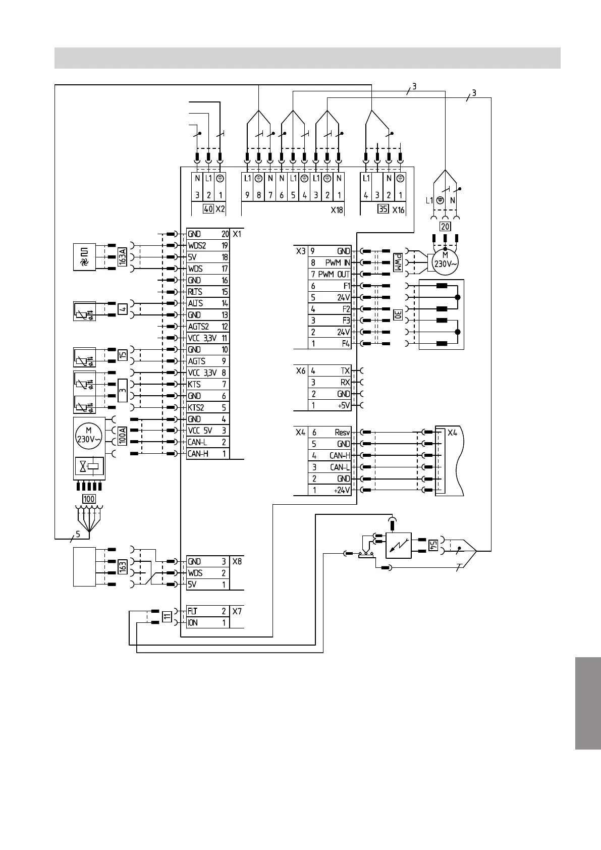
123
Fig. 71
PWM Control signal
X... Electrical interfaces
§
A/B
Flow temperature sensors 1 and 2
$
Outlet temperature sensor (gas condensing
combi boiler)
aA
Ionisation electrode
aG
Flue gas temperature sensor
sÖ
Internal circulation pump (primary circuit pump)
dÖ
3-way diverter valve
dG
Gas solenoid valve
fÖ
Power supply
gF
Ignition unit
a-Ö
Fan motor
a-Ö
A
Fan motor control
aND
Water pressure sensor
aND
A
DHW flow sensor
A
BCU burner control unit
B
HMU heat management unit (plug
aBH
)
C
HMU heat management unit (plug X4)
Connection and wiring diagram
BCU burner control unit
5593201
Appendix