27
Assigning functions in the commissioning assis-
tant
See commissioning assistant in "Commissioning".
Information on connecting PlusBus subscribers
Only the following PlusBus subscribers can be connec-
ted to the control:
■
2 x EM-M1 or EM-MX extensions (ADIO electronics
module)
■
2 Vitotrol 200-E
■
3 x EM-EA1 extensions (DIO electronics module)
■
1 x EM-S1 extension (ADIO or SDIO/SM1A electron-
ics module)
■
1 x EM-P1 extension (ADIO electronics module)
The max. total length of the PlusBus lead is 50 m.
With an unscreened lead, 2-core, 0.34 mm
2
.
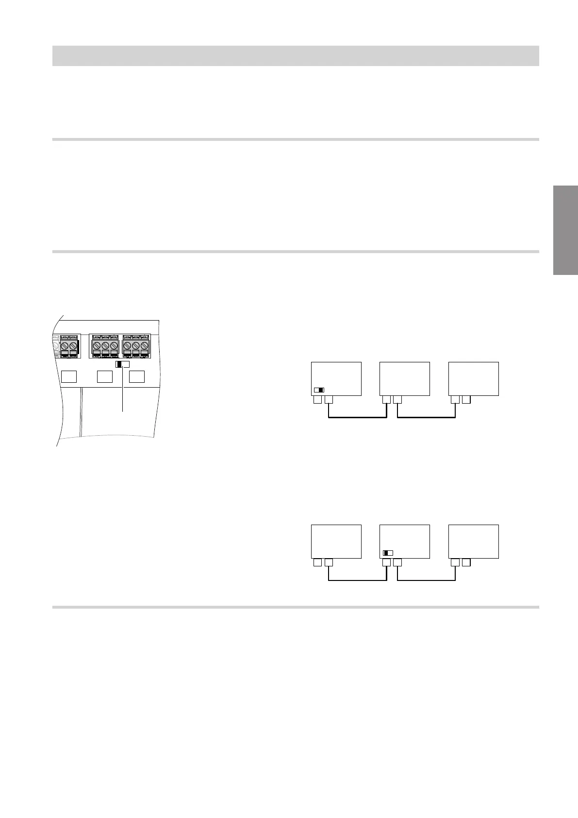
Checking the CAN bus terminator switch setting
The CAN bus resistor is switched using switch A
in
the wiring chamber.
Fig. 18
■
If the device is not integrated into a CAN bus sys-
tem:
Switch
A
must not be set to "ON".
■
If the device is integrated into a CAN bus system and
is located at the beginning or end of this system (not
in the middle) of the CAN bus system (connected to
only one plug
lA
): Set switch
A
to "ON".
Fig. 19
A Heat generator / HMU heat management unit
B CAN bus cable
C CAN bus other subscribers
■
If the device is integrated into a CAN bus system and
is not located at the beginning or end of the CAN
bus system (both plugs
lA
connected): Do not set
switch
A
to "ON".
Fig. 20
Power supply for accessories at plug lH/aBH (230 V ~)
When positioned in wet rooms, accessories outside
the wet area must not be connected to the power sup-
ply at the HMU heat management unit. If the boiler is
not sited in a wet room, the power supply for accesso-
ries can be connected directly to the HMU heat man-
agement unit. This connection is switched directly with
the ON/OFF switch of the appliance.
If the total system current exceeds 6 A, connect one or
more extensions directly to the mains supply via an
ON/OFF switch (see next chapter).
Installation sequence
Electrical connections (cont.)
5593201
Installation