19
1. Remove the hinges and store them in case they
need to be reinstalled at a later date.
4. Pull the plug of the connecting cable from the
bracket.
!
Please note
Incorrect routing of the cable can lead to
heat damage and impairment of the EMC
properties.
Do not change the position of the cable or its
fixture (fixing point on casing).
6. Turn the bracket over and insert the plug on the
right-hand side again.
Connections on the heating water and DHW sides
If the connections have not been fitted previously,
make the connections on the heating water and DHW
sides.
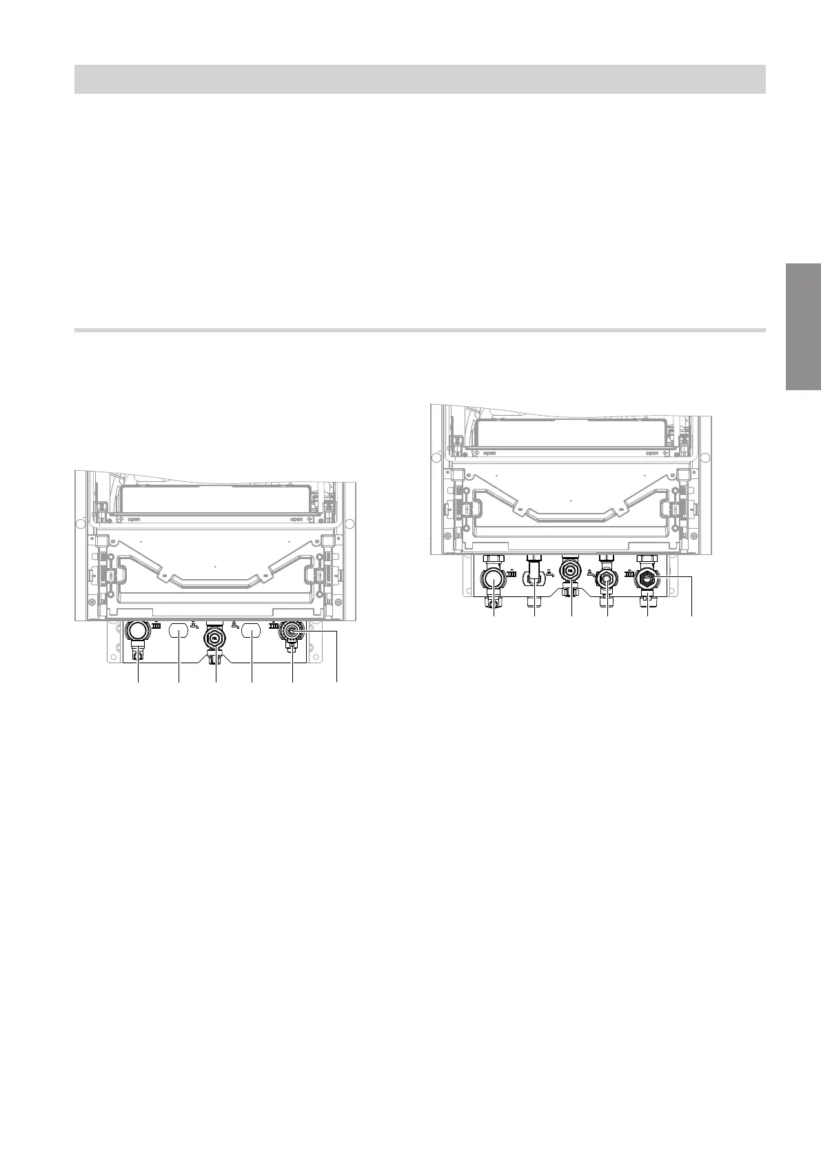
Gas condensing system boiler
Fig. 8 Specifications for threads in conjunction with
connection accessories
A
Heating flow R ¾ (male thread)
B
Cylinder flow G ¾ (male thread)
C
Gas connection R ¾ (male thread)
D
Cylinder return G ¾ (male thread)
E
Heating return R ¾ (male thread)
F
Filling/draining
Connection on the heating water side of the DHW
cylinder:
The required intermediate pieces (Rp ¾, female
thread) on the cylinder flow and return are part of the
connection set for the DHW cylinder.
If no DHW cylinder is being connected, seal off the
connections with caps.
Gas condensing combi boiler
Fig. 9 Specifications for threads in conjunction with
connection accessories
A
Heating flow R ¾ (male thread)
B
DHW R ½ (male thread)
C
Gas connection R ¾ (male thread)
D
Cold water R ½ (male thread)
E
Heating return R ¾ (male thread)
F
Filling/draining
Scald protection
DHW temperatures of over 60 °C can occur with gas
condensing combi boilers. As a result, scald protection
should be installed on site in the DHW pipe.
Installation sequence
Mounting the boiler and making connections (cont.)
5593201
Installation