14
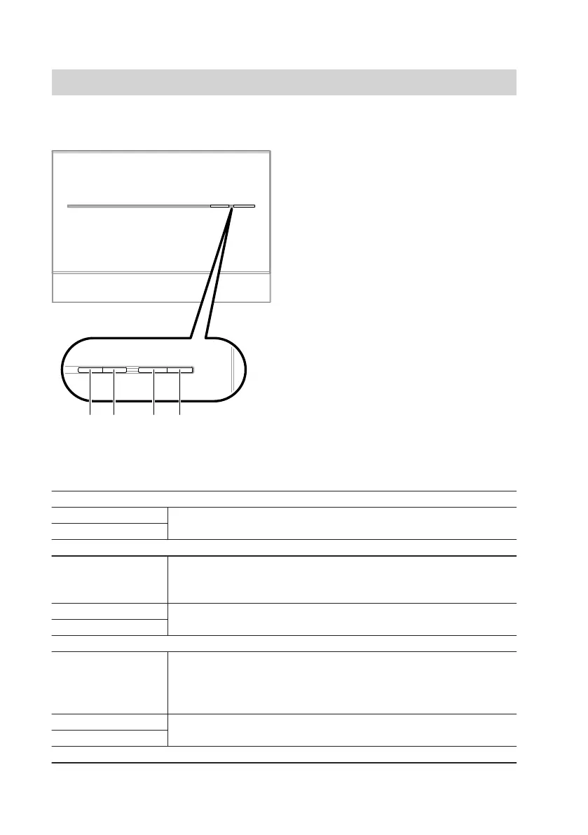
With cover
"T1" Maintenance button (only for heat-
ing contractors)
"2" Field strength indicator (yellow,
green and red LEDs)
"3" Indicator for mobile network con-
nection status (yellow and green
LEDs)
"4" Operating status indicator (green
and red LED)
Interpreting the LED indicators
PIN entry indicator "1"
Flashes green Only for PIN entry (see page 27).
Illuminates green
Field strength indicator "2"
Flashes yellow/
flashes red/illumi-
nates red
Field strength indicator (see page 15)
SIM card fault (see page 38)
Flashes green Only for PIN entry (see page 27).
Illuminates green
Indicator for mobile network connection status "3"
Flashes yellow/illu-
minates yellow
■ Establishing a connection to a mobile network or connection
fault (see page 37)
or
■ SIM card fault (see page 38)
Illuminates green Only for PIN entry (see page 27).
Flashes green
Operating status indicator "4"
Operating the device
Display and control elements
(cont.)
5782 277 GB