To avoid risk of electrical shock, personal injury, or death, disconnect electrical power source to unit, unless test
procedures require power to be connected. Discharge capacitor through a resistor before attempting to service.
Ensure all ground wires are connected before certifying unit as repaired and/or operational.
WARNING!
Disassembly
©2012 Viking Preferred Service 15
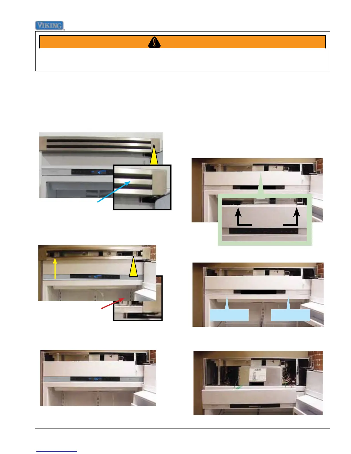
The control panel has an overlay switch
attached to it that allows user input to the
control boards.
1. To access the control panel, remove the
upper air grill assembly (see Upper Grill
Removal section), remove (2) screws
securing the control panel.
Control Panel
Screws
2. Pull control panel from securing tabs.
3. Lower the control panel. Take caution with
the ribbon cable to prevent damage.
Securing tabSecuring tab
Removal of the upper grille assembly allows
access to the control assembly.
1. To remove the upper grille assembly, slide
out the middle air louver.
Upper Grille Assembly
Middle Air Louver
2. With the middle grille louver removed,
remove the (2) 1/4" hex screws securing
the grille assembly.
Remove 1/4" screw
on each side
3. Remove the grille assembly