To avoid risk of electrical shock, personal injury, or death, disconnect electrical power source to unit, unless test
procedures require power to be connected. Discharge capacitor through a resistor before attempting to service.
Ensure all ground wires are connected before certifying unit as repaired and/or operational.
WARNING!
Troubleshooting
42 ©2012 Viking Preferred Service
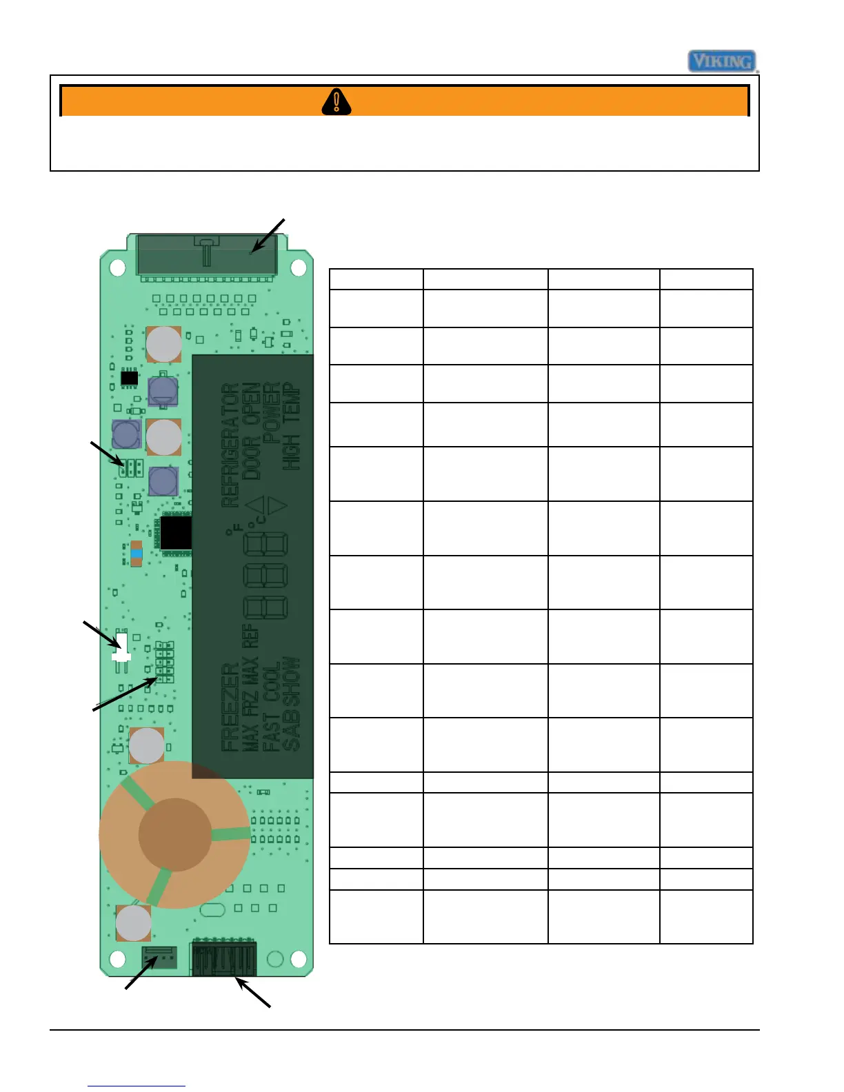
P4
P9
P5
P8
P3
J7
Pin location Function Voltage range Signal
P4-1 Dc supply to
thermistors
4.5 - 5.5 VDC,
ref to P4-12
DC
P4-2 Freezer thermistor
input
0 - 5.5 VDC, ref
to P4-12
DC
P4-3 Refrigerator
thermistor input
0 - 5.5 VDC, ref
to P4-12
DC
P4-4 Provide zero
timing
26 V p-p to 34V
p-p, ref P4-12
See Note 1
below
P4-5 DC Fan enable 17.8 vdc - 38
vdc, ref to
chassis grnd.
DC
P4-6 Defrost
termination
17.8 vdc - 38
vdc, ref to
chassis grnd.
See Note 2
below
P4-7 Evaporator fan
enable
17.8 vdc - 38
vdc, ref to chas-
sis ground
See Note 2
below
P4-8 Compressor
enable
17.8 vdc - 38
vdc, ref to chas-
sis ground
See Note 2
below
P4-9 Defrost termina-
tion signal
25.8 vdc - 38
vdc, ref to chas-
sis grnd
See Note 2
below
P4-10 Door signal 25.8 vdc - 38
vdc, ref to chas-
sis grnd
See Note 2
below
P4-11 PS Reference 0 vdc DC
P4-12 -30 vdc 22.8 vdc - 38
vdc, ref to chas-
sis ground
See Note 2
below
P4-13 Not used AC
P4-14 Not used AC
P4-15 Light enable relay 17.8 vdc - 38
vdc, ref to chas-
sis ground
See Note 2
below
Low Voltage Board
NOTE 1 : Requires an oscilloscope to measure
NOTE 2 :DC voltage- load of meter can affect measurement