EasyManua.ls Logo

Viking VISC530 User Manual

Viking VISC530
53 pages
To Next Page IconTo Next Page
Page #1 background imageLoading...
Page #1 background image
Preferred Service
SMC-0011
May 2009
This manual covers general and
specific information including, but not
limited to the following model:
VISC530
Professional
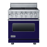
30" Electric
Induction Range
Service
Manual
This manual is to be used by qualified appliance technicians only.
Viking does not assume any responsibility for property damage
or personal injury for improper service procedures done by an
unqualified person.

Table of Contents

Questions and Answers:

Viking VISC530 Specifications

General IconGeneral
BrandViking
ModelVISC530
CategoryRanges
LanguageEnglish

Summary

Important Information

Safety Information

Guidance on safety messages and alert symbols used throughout the manual.

Hazard Definitions

Defines safety alert symbols and terms like DANGER, WARNING, and CAUTION for hazard communication.

Warranty Information

Product Warranty Details

Details the One Year Full Warranty, Five Year Limited Warranty, and Ten Year Limited Warranty.

Warranty Service Procedures

Obtaining Warranty Service

Explains how to obtain warranty service and requirements for authorized service.

General Warnings and Safety

Appliance Usage Warnings

Details critical safety warnings regarding appliance usage, fire prevention, and heating elements.

Fire Safety Instructions

Provides instructions on how to handle fires that may occur with the appliance.

Oven Operation and Safety

Electrical Shock Hazard Warnings

Highlights electrical shock hazards related to bulb replacement.

Operation: Oven Cooking

Oven Functions and Settings

Details the various oven modes like BAKE, CONV BAKE, TRU CONV, CONV ROAST, CONV BROIL, HI/MED/LOW BROIL, SELF CLEAN, and Dehydration/Defrost.

Self-Clean Cycle and Power Failures

Self-Clean Cycle Operation

Explains the automatic pyrolytic self-cleaning cycle, including smoke elimination and door latch operation.

Diagnostics: Built-In Error Codes

Error Codes for Burner Switches

Details error codes displayed on the thermostat timer digital display for burner switch issues.

Diagnostics: Error Code Details

Filter Board, Sensor, and Wiring Errors

Continues error code list covering filter board issues, sensor defects, and wiring problems.

Induction Operation Theory

Oven LED Error Codes

Explains how error codes are displayed using cycle and clean lights on the oven control panel.

Induction Mechanics and Safety

Induction Safety Features

Details built-in safety features of induction cooking, including pot detection, cool surfaces, and thermal protection.

Service Diagnostics and Procedures: Parts Location

Oven Control Board Component Layout

Provides a detailed diagram showing the location of various connectors and components on the oven control board.

Service Diagnostics and Procedures: Control Board Access

Control Board Removal Procedure

Details marking, disconnecting, and removing the control board from its mounting plate.

Service Diagnostics and Procedures: Control Board Testing

Bake and Broil Element Testing

Explains diagnosing Bake and Broil elements using resistance measurements from control board connectors.

Convection Element & Cooling Fan Testing

Details diagnostic procedures for Convection Element and Cooling Fan using resistance and voltage checks.

Convection Fan & Door Lock Motor Testing

Covers resistance testing for Convection Fan and Door Lock Motor connected to the control board.

Thermostat and Selector Switch Testing

Explains testing Thermostat and Selector switches using resistance and voltage measurements.

RTD Sensor Resistance Testing

Details the resistance testing procedure for the RTD Sensor connected to the control board.

Service Diagnostics and Procedures: Component Testing

Door Lock System Testing

Explains door lock system operation and how to test the door lock motor and switches.

Service Diagnostics and Procedures: Disassembly

Service Diagnostics and Procedures: Component Replacement

Service Diagnostics: Component Testing

Diagnostics: Inductor and Sensor

Service Diagnostics: Component Testing

Comprehensive Component Testing Chart

Provides a chart detailing components, voltage, resistance, amperage, and test locations for diagnostics.

Service Diagnostics: Troubleshooting Guide

Troubleshooting Coil and Power Issues

Offers a guide to common problems, probable causes, and corrections for coil and power-related malfunctions.

Troubleshooting Oven Operation and Lights

Continues troubleshooting for oven operation, lights, door lock, and blower motor issues.

Wiring and Schematics: Overall Diagram

VISC 530 Wiring Diagram

Presents the overall wiring diagram for the VISC 530 model, showing interconnected components and power flow.

Related product manuals