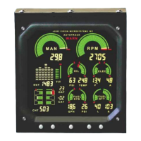
Page 8 Vision Microsystems Incorporated
Lycoming engines during setup. Full color graphics make detection
of cylinder operating status easy. The digital display defaults to the
hottest CHT. For example, if CHT 1 is the hottest, the digital
display will show H1 periodically.
Pressing will cycle through each CHT and the hottest and allow
you to select a different CHT by choosing C1, C2 etc. After power
up or after a peak find operation, the digital display defaults to show
the hottest CHT. Temperature is displayed in either Fahrenheit or
Celsius units (as set in the MISCELLANEOUS menu).
CHT Alert: warning system will flash if a CHT limit is exceeded
(as set in ENGINE LIMITS ). For over temperature both the graphic
and digital will flash. A lowercase h1 would identify CHT1 as
exceeding the maximum redline temperature. For shock cooling a
flashing lowercase c1 would identify CHT1 as exceeding the
maximum cool down rate (as set in MISCELLANEOUS menu).
EGT Analyzer System Operation
The EGT ANALYZER system displays all EGTs graphically. EGT
probes are periodically tested by the system and any probe that is
detected as bad will be shut off. Peaking mode is not allowed if a
bad probe (including a TIT probe) is detected. An EGT over-
temperature (as set in ENGINE LIMITS) will cancel and disallow
peaking mode until corrected.
The system can operate in either of two leaning modes: Rich of
Peak or Lean of Peak. This is selected during initial system setup.
After power up, the EGT digital display defaults to EGT 1 (unless
you have enabled the TIT system - see Turbo Inlet Temperature
System Operation). Periodically the digital display will identify
which EGT you are seeing by showing and E followed by the EGT
number, such as E1 for EGT 1. After you have successfully leaned
the engine (as an example, lets assume it was EGT 2), the digital
readout is locked to that EGT and E1 will change to P2 signifying
that it peaked on EGT 2.

 Loading...