Page 32 Vision Microsystems Incorporated
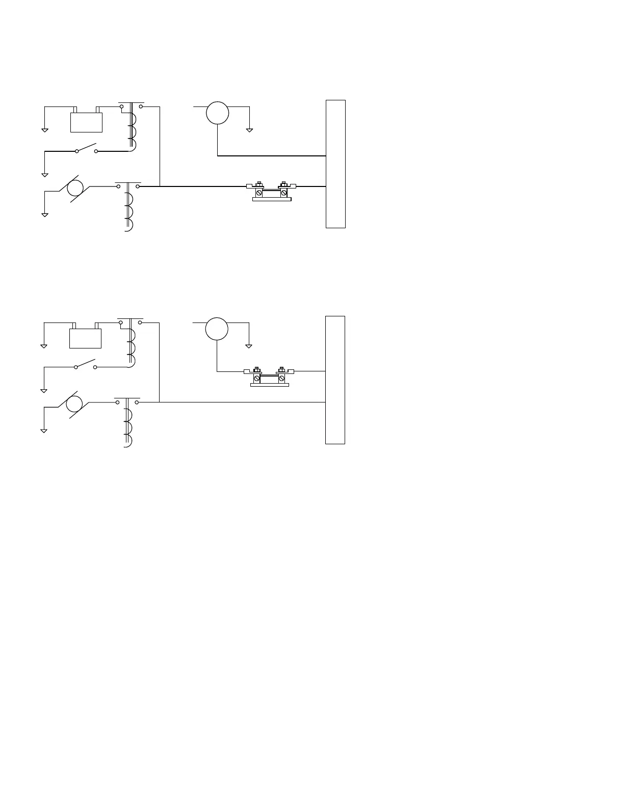
ammeter configuration. The alarm will be triggered by a discharge
condition.
- BATT +
Master switch
Starter Starter solenoid
Master switch
contactor
Bus
F G
B
external shunt
Ammeter Configuration
Alternator
+
Load Meter configuration. The shunt must be installed between the
alternator output and the main bus. Be sure that the negative side of the
shunt is connected to the main bus in the load meter configuration.
- BATT +
Master switch
Starter Starter solenoid
Master switch
contactor
Bus
F G
B
external shunt
PN MS 91586-6
Load Meter Configuration
Alternator
+
Capacitive Fuel Level Sender Installation
Do not install probe into metal mounting flange without first applying
thread lubricant or damage will occur. Insure all threads are free from
burrs and debris.