VM1000C Pilot’s Guide Page
27
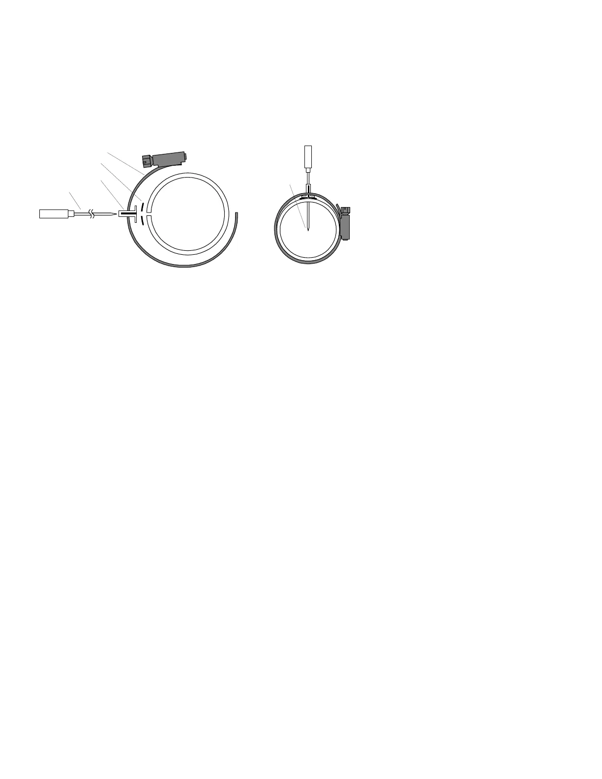
drilling to ensure that nothing interferes with the probe, clamp, screw or
wire. Careful matching of probe position will provide best temperature
measurements.
Insert the probe in the exhaust or previously drilled hole so that the tip of
the probe is in the center of the exhaust stream. Tighten the stainless
steel clamp to a torque of 45 in/Lbs. Cut off the excess strap close to the
screw.
Position probe
in approximate
center of
exhaust
Probe
Clamp
Thimble
note orientation of
slot
Seal Washer
Turbine Inlet Temperature (TIT) Probe Installation (Optional)
Use the J1 connector harness 700200 and insert the yellow wire into the
connector pin 16 and the red wire into pin 17. The standard TIT probe PN
M111-T with a #48 clamp is placed in the exhaust stack accumulator to a
maximum depth of 1/2 inch and approximately 4 inches from the turbine
inlet if possible, on the waste-gate side of the turbine.
TIT for second Turbine Inlet Temperature
Use the J1 connector harness 700200 and insert the yellow wire into the
connector pin 18 and the red wire into pin 17The standard VISION
MICROSYSTEMS TIT probe P/N M-111-T with a special clamp is placed
in the exhaust stack accumulator to a maximum depth of 1/2 inch and
approximately four inches from the Turbine inlet if possible, on the waste
gate side of the turbine.
Cylinder Head Temperature (CHT) Probe Installation
Use the J2 connector harness 700700 or 700702 labeled C1 through C4
or C6. The VISION MICROSYSTEMS probe is a bayonet probe P/N
5050-T that has a captive 3/8-24 boss that is screwed into the head of
each cylinder.