Page 26 Vision Microsystems Incorporated
The most common installation problems are related to poor quality
terminations.
Wiring Markings
The VM1000C is supplied with special Teflon insulated Chromel- Alumel
factory assembled wiring harness configured for the correct number of
cylinders. The wire harness is marked E1= EGT-1, C1= CHT-1, etc.
NOTE: Unlike most other EGT & CHT installations the probe wire
length is not critical and should be trimmed to any length as required
for a clean installation. Do not extend the thermocouple wire with
copper wire.
Exhaust Gas Temperature Probe (EGT) Installation
Use the J2 connector harness 700700 or 700702 labeled E1 through E4
or E6. Remove the existing EGT gage and Probe. Replace with VISION
MICROSYSTEMS probe M-111 in all exhaust stacks.
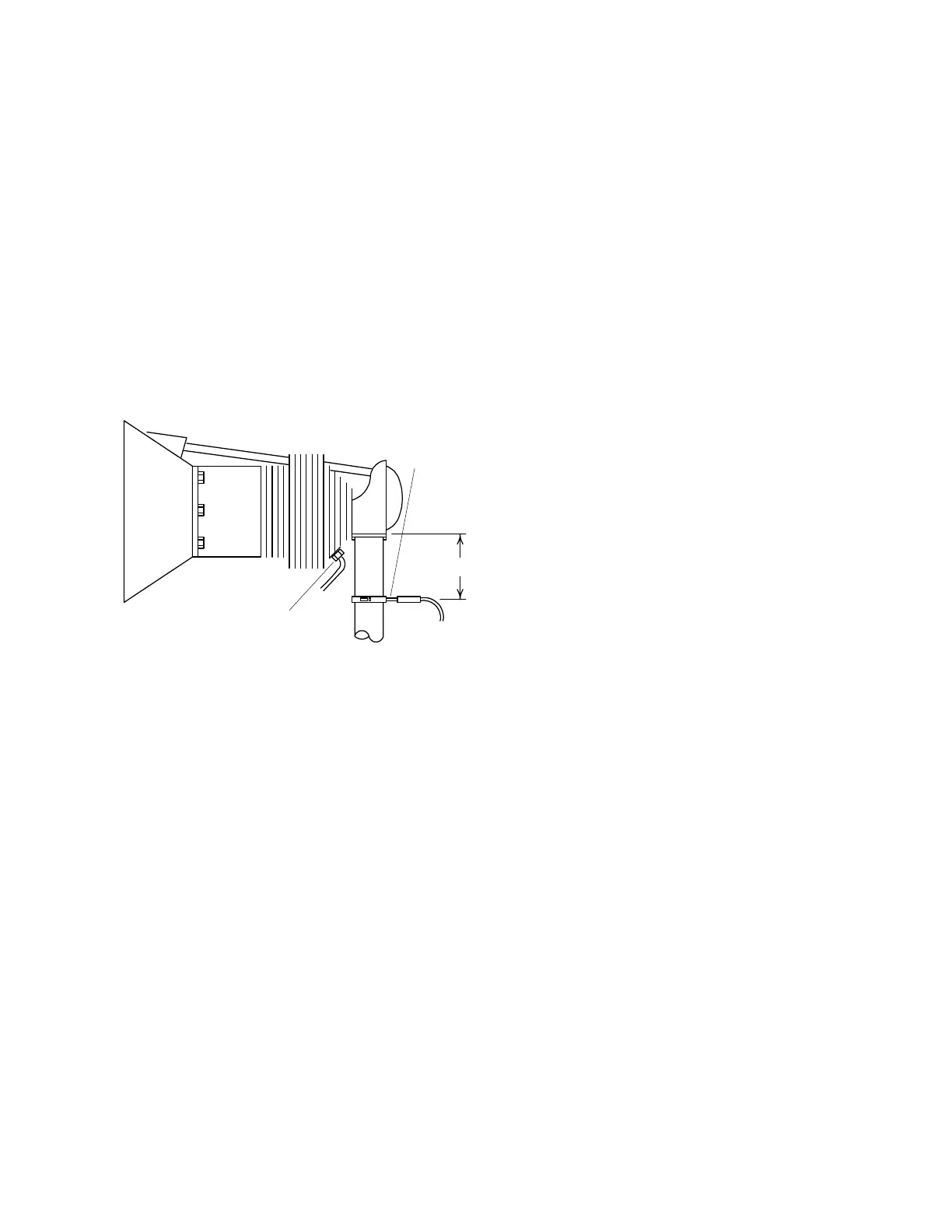
2" to 4"
EGT probe
Drill no. 40
pilot hole,
then no. 30
hole.
CHT probe
exhaust stack
The Model M-111 Probe will fit any engines where the existing holes in
the exhaust stack are 1/8" to 1/4" in diameter. If no hole exists, it will
require the drilling of a 1/8" diameter hole and ream to fit. It is important
that each probe be mounted the same distance from its exhaust stack
flange. A nominal distance of 2 to 4 inches from the exhaust flange is
recommended. If the recommended distance is impractical because
of obstructions, slip joints or bends in the exhaust system then position
the probes a uniform distance from the flange as space permits. Do not
mount probes in slip joints. Be certain to locate all holes BEFORE