VM1000C Pilot’s Guide Page
25
Probe Wiring
Note: use only probes supplied with this unit. Older Vision
Microsystems probes are not compatible with this instrument.
When cutting the pair of leads to the proper length to connect to the
probes, leave enough slack in the wiring so that probe may be
interchanged to an adjacent cylinder if necessary for trouble-shooting and
servicing. Thermocouple wire length is not critical and should be trimmed
to any length as required for a clean installation.
The Temperature probe must be wired with the correct polarity. The
temperature probe connects to its temperature indicator with yellow
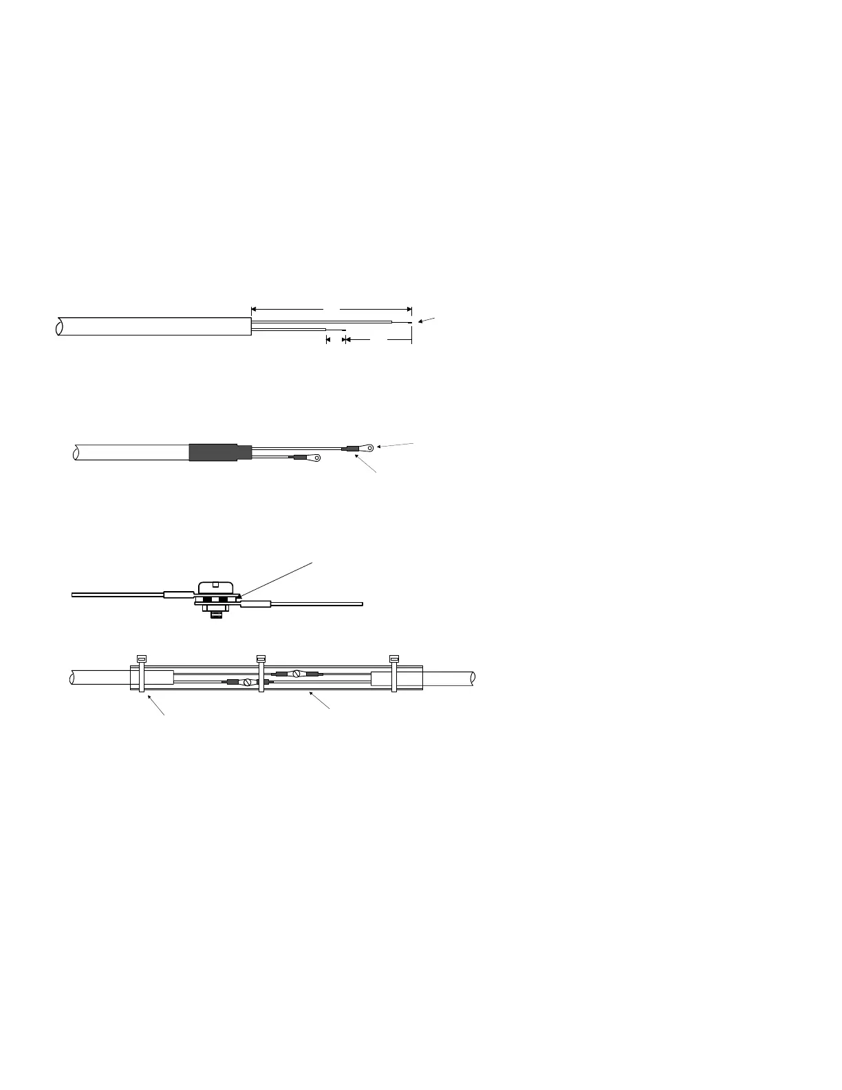
jacket Teflon Chromel-Alumel wire supplied. Strip the wires as shown
below—observing color-coding.
1/4" 1 1/2"
Fold back wire
double before
crimping terminals
2 1/4"
Thermocouple wire harness
red
yellow
Terminate each wire with a crimp-on ring terminal, provided. The ring
terminals may be crimped with a “service-type” tool, however AMP part
number 48518 crimp tool is recommended. Verify the quality of each
crimp with a sharp tug on the wire. The terminal should be impossible to
pull off when crimped correctly.
shrink tubing
Place a ¼ x 4-inch sleeve over each pair of wires in the wiring. Connect
the wire ring lug to the probe ring lug using the supplied number 4 screws
and nuts, placing the star washer between the ring lugs, not against the
nut.
Important: place star waster between two ring
terminals and tighten nut and bolt as
necessary
to instrument
to probe
Slide the sleeve over the joint and secure with three tie-wraps.
1/4 x 4" sleeve
tie-wrap 3 places