VM1000C Pilot’s Guide Page
35
the black wire to the terminal mounted on the metal body on the sender.
Repeat for the other tank sender.
Resistive Fuel Level Sender Installation
Disconnect the fuel level senders from the aircraft’s existing wiring
harness, and connect them to the VISION MICROSYSTEMS supplied
harnesses as described below. Make sure they do not have voltage on
them before connecting to the VM1000C.
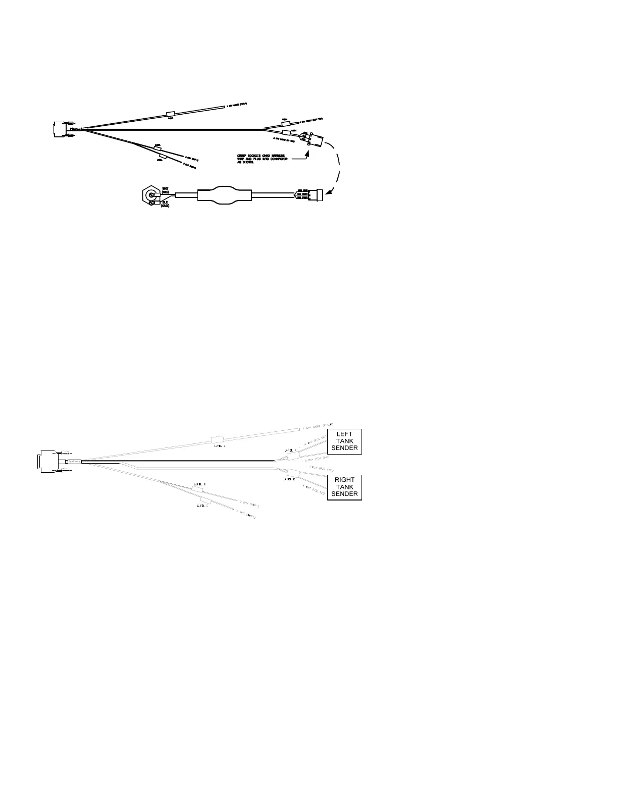
Use J5 connector harness 700719-3 with two black wire pairs labeled
LEFT TNK RES and RT TANK RES. On installed sensors connect them
to the J5 FP/FQ/AMP wiring harness as shown below. Connect the white
wire to the signal terminal and black wire to the ground terminal of the
resistive fuel level sensor. Tank setup 1- Record the sender resistance at
full (top off). 2 – Burn off or remove approximately ½ tank, and record the
resistance. For greater accuracy use the AFM to determine the
Calibration point at Zero fuel. Now with the tank size you can create an
input table. Repeat for the other tank sender.