3. POWERMASTER-10 G2 INSTALLATION
D-304762 PowerMaster-10/30 G2 Installer's Guide
11
3.5 PGM-5 Installation
PGM-5 is an output interface module designed to provide alarm, trouble events and status signals to external devices
such as long range wireless monitoring transmitters, CCTV systems, home-automation systems and LED annunciation
panels (for further details see the PGM-5 Installation Instructions).
The PGM-5 provides 5 solid state relay contact outputs and is designed to be used as a plug-in internal add-on module
with the PowerMaster-10 G2 control panel.
Notes:
1. The PGM-5 will be active only if the PGM-5 option was enabled in the factory default of the control panel.
2. PGM-5 plug-in module not enabled in UL Listed product.
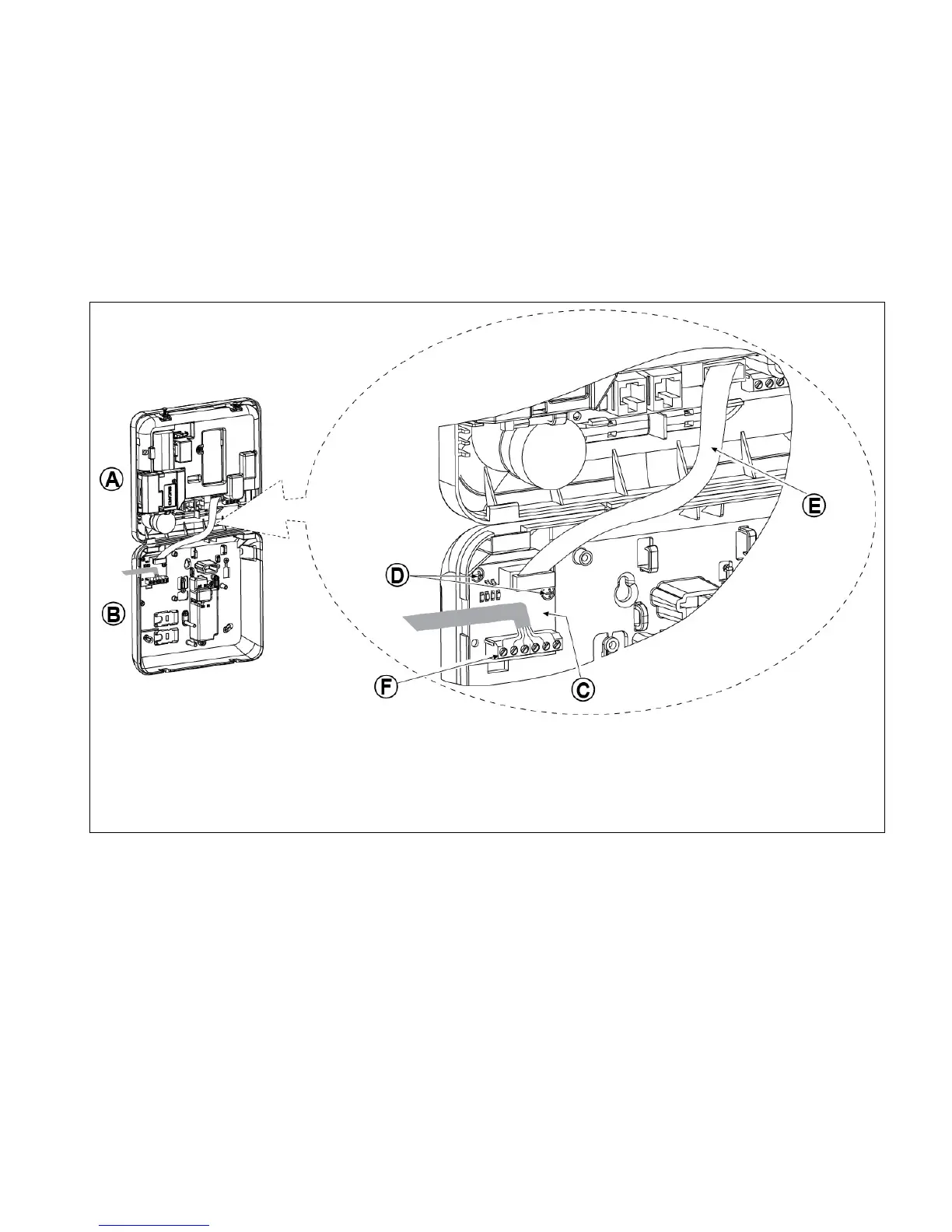
Caution! When mounting the PGM-5 module it is strongly recommended to route the cable as shown in Figure 3.5 to
prevent interference which may occur if routed too close to the control panel antennas.
A. Front unit
B. Back unit
C. PGM-5 Module
D. 2 Screws for fastening the PGM-5 Module
E. Flat cable
F. Wiring
Figure 3.5 – PGM-5 Module Mounting

 Loading...


