4. POWERMASTER-30 G2 INSTALLATION
24
D-304762 PowerMaster-10/30 G2 Installer's Guide
The 12V and "GND" terminals can be connected to a siren (for constant DC power supply).
*** The.12V supply to the PGM device is fused. Current is limited to 100 mA.
WARNING! When plugging terminals back into place, be sure to align them carefully with the pins on the PCB.
Misaligned or reverse insertion of terminals may damage internal PowerMaster-30 G2 circuits!
IMPORTANT! The terminals for internal and external sirens are DC outputs intended for 12V sirens. Connecting a
loudspeaker to any of these outputs will cause a short circuit and will damage the unit.
Notes for UL installations:
1. A device that is connected to PGM terminal should not be programmed to be activated during standby.
2. The system shall be installed in accordance with CSAC22.1 Canadian Electrical Code, Part 1.
3. A minimum spacing of 1/4 inch shall be maintained between the telephone wiring and the low voltage wiring (zones,
bell circuit, etc.) Do not route the LINE and SET wires in the same wiring channel with other wires.
4. Do not connect to a receptacle controlled by a switch.
5. Hard wired zones are for BURG use only.
6. Alarm Contact (F) and/or Magnetic Contact must be UL Listed.
7. Minimum System Configuration for BURG consists of: Control Panel (PowerMaster-10 G2 or PowerMaster-30 G2).
Intrusion Detection Device
(Magnetic Contact, PIR, Wired Zone etc) compatible UL Listed Monitoring Station
Receiver.
8. Minimum System Configuration for FIRE consists of: Control Panel (PowerMaster-10 G2 or PowerMaster-30 G2).
Zone etc, Smoke Detector (SMD-426/427 PG2), compatible UL Listed Monitoring Station Receiver.
4.10 Connecting Power to the Control Panel
Notes:
1. Do not use mains cable (3 m long) or power supply other than that supplied by the manufacturer LEADER
ELECTRONICS, model no. MU24-11125-A10F. For UL installations, model no. MU15-R125120-A1, p/n MU15-R1125-
A00S. For ULC installations, model no. MU15- R125120-A1, p/n MU15-R1125-A01S.
2. For UL installations (UL), the plug-in transformer must have restraining means. For Canada (CUL), it cannot have
restraining means.
3. This equipment should be installed in accordance with Chapter 2 of the National Fire Alarm Code, ANSI/NFPA 72 and
CAN/ULC-S540.
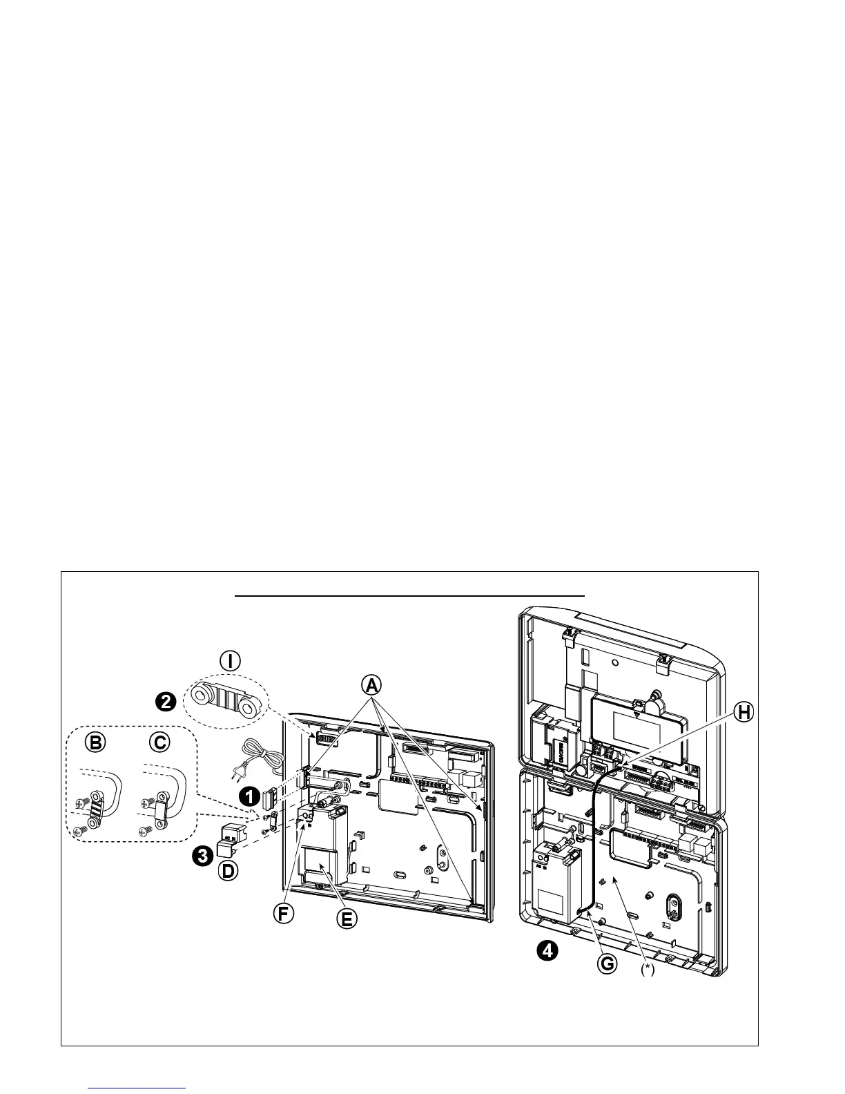
Connect the power cable and close the control panel as shown in Figures 4.10a – 4.10b.
POWER CONNECTION FOR INTERNAL POWER SUPPLY

 Loading...


