4. POWERMASTER-30 G2 INSTALLATION
26
D-304762 PowerMaster-10/30 G2 Installer's Guide
4.12 Supplying Power to the Unit
Connect power to the PowerMaster-30 G2 temporarily (see Figure 4.10). Alternatively, you may power up from the
backup battery, as shown in Figure 4.11.
Disregard any “trouble” indications pertaining to lack of battery or lack of telephone line connection.
For Europe Safety Compliance:
a. The model shall be installed according to the local electrical code.
b. The circuit breaker shall be readily accessible.
c. The rating of the external circuit breaker shall be 16A or less.
Please refer to Figure 4.11 "Battery Insertion".
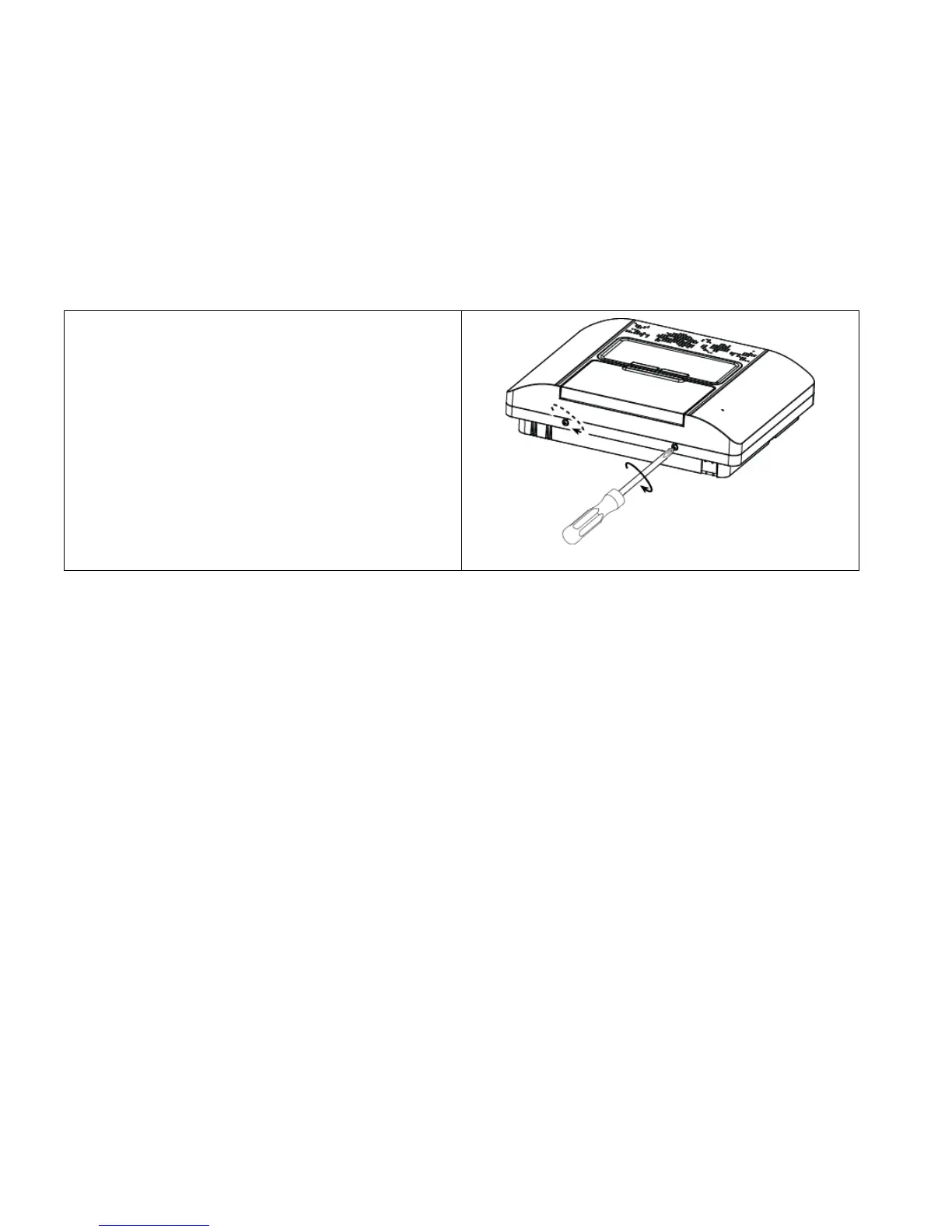
4.13 Closing the PowerMaster-30 G2 Control Panel
Control panel final closure is shown below.
To Close the Control Panel:
1. Connect the flat cables, between front and back units,
in their respective connectors (up to 3, according to
options).
2. Close the panel and fasten the 2 screws.
3. Switch on the control panel; make sure that the
"Power" indicator on the control panel lights green.
Figure 4.13
- Final Closure

 Loading...


