3. POWERMASTER-10 G2 INSTALLATION
8
D-304762 PowerMaster-10/30 G2 Installer's Guide
3. POWERMASTER-10 G2 INSTALLATION
Required tool: Philips screwdriver #2.
PowerMaster-10 mounting process is shown in Figures 3.1 - 3.9.
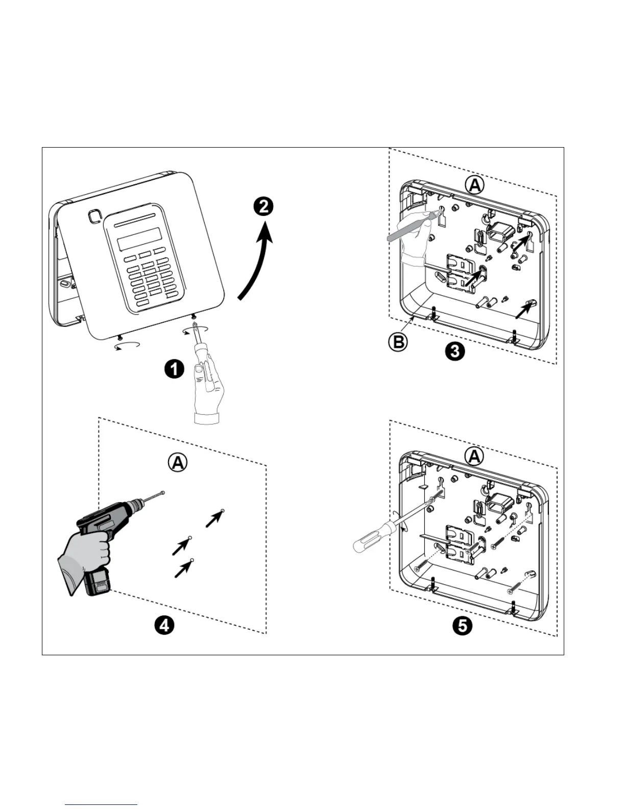
3.1 Opening the PowerMaster-10 G2 Control Panel and Bracket Mounting
Figure 3.1 – Back Unit Mounting
To Mount the Unit:
1. Release the screws A. Mounting surface
2. Remove the front cover B. Back unit
3. Mark 4 drilling points on the mounting surface
4. Drill 4 holes and insert wall anchors
5. Fasten the back unit with 4 screws
WARNING! When plugging SIREN & ZONE terminals back into place, be sure to align them carefully with the pins on the
PCB. Misaligned or reverse insertion of terminals may cause internal damage to the PowerMaster-10 G2!