3. POWERMASTER-10 G2 INSTALLATION
D-304762 PowerMaster-10/30 G2 Installer's Guide
13
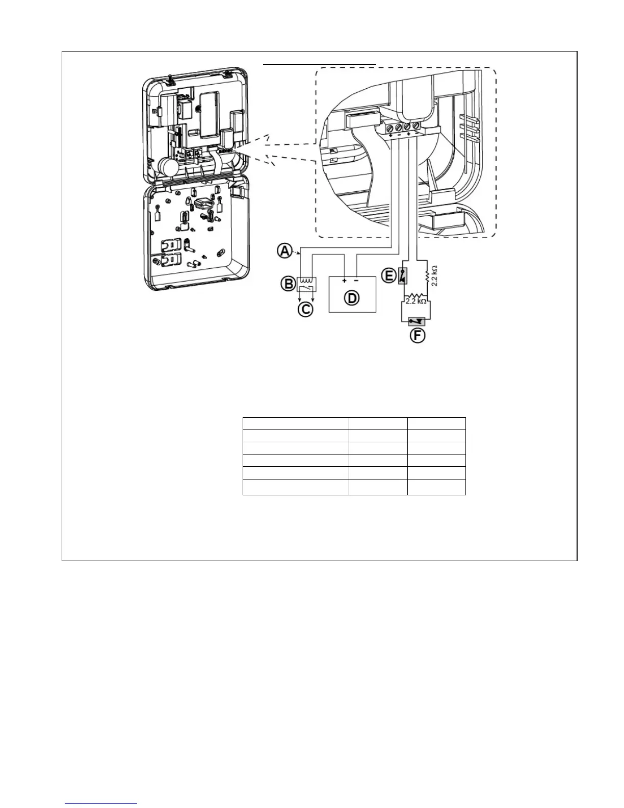
PGM AND ZONE WIRING
A. PGM output**
Vmax=30v
Imax=100mA
B. Relay**
C. Device**
D. External power supply 5 -
30VDC
∗∗
E. Wired detector's Tamper
∗
F. Wired detector's alarm or
Arming Key (see section
5.4.2, “Zone Type List”
table).
∗
For UL installations, E must be
UL listed.
∗∗
PGM: not to be enabled in UL
listed product.
Note:
The wired detector should be installed at least 2 meters away from the
control panel.
Regarding the wired zone, the control panel classifies the events according
to the resistance it measures as shown in the table below.
E.O.L or Arming Key Resistance
Range Zone Arming Key
5.26 kΩ
Alarm Disarm
∼5.26 kΩ ↔
∞
Tamper Tamper
Notes:
1. The E.O.L resistors are 2.2 kΩ resistors of 1/4 W, 5% supplied with the
panel and are UL listed under the name EOLR-3, kit number 57000850.
2. If the Arming Key is enabled, the wired zone must be located in the
protected area.
Figure 3.6b – PGM & Zone Wiring
Notes for UL installations:
1. A device that is connected to PGM terminal should not be programmed to be activated during standby.
2. The system shall be installed in accordance with CSA C22.1 Canadian Electrical Code, Part 1.
3. A minimum spacing of 1/4 inch shall be maintained between the telephone wiring and the low voltage wiring (zones,
bell circuit, etc.). Do not route the LINE and SET wires in the same wiring channel with other wires.
4. Do not connect to a receptacle controlled by a switch.
5. Hard wired zones are for BURG use only.
6. Tamper (E) must be UL Listed.
7. Minimum System Configuration for BURG consists of: Control Panel (PowerMaster-10 G2 or PowerMaster-30 G2).
Intrusion Detection Device
(Magnetic Contact, PIR, Wired Zone etc) compatible UL Listed Monitoring Station
Receiver.
8. Minimum System Configuration for FIRE consists of: Control Panel (PowerMaster-10 G2 or PowerMaster-30 G2).
Zone etc, Smoke Detector (SMD-426/427 PG2), compatible UL Listed Monitoring Station Receiver.

 Loading...


