5 Wiring and Terminations
5.1 Example Vehicle Wiring Diagram
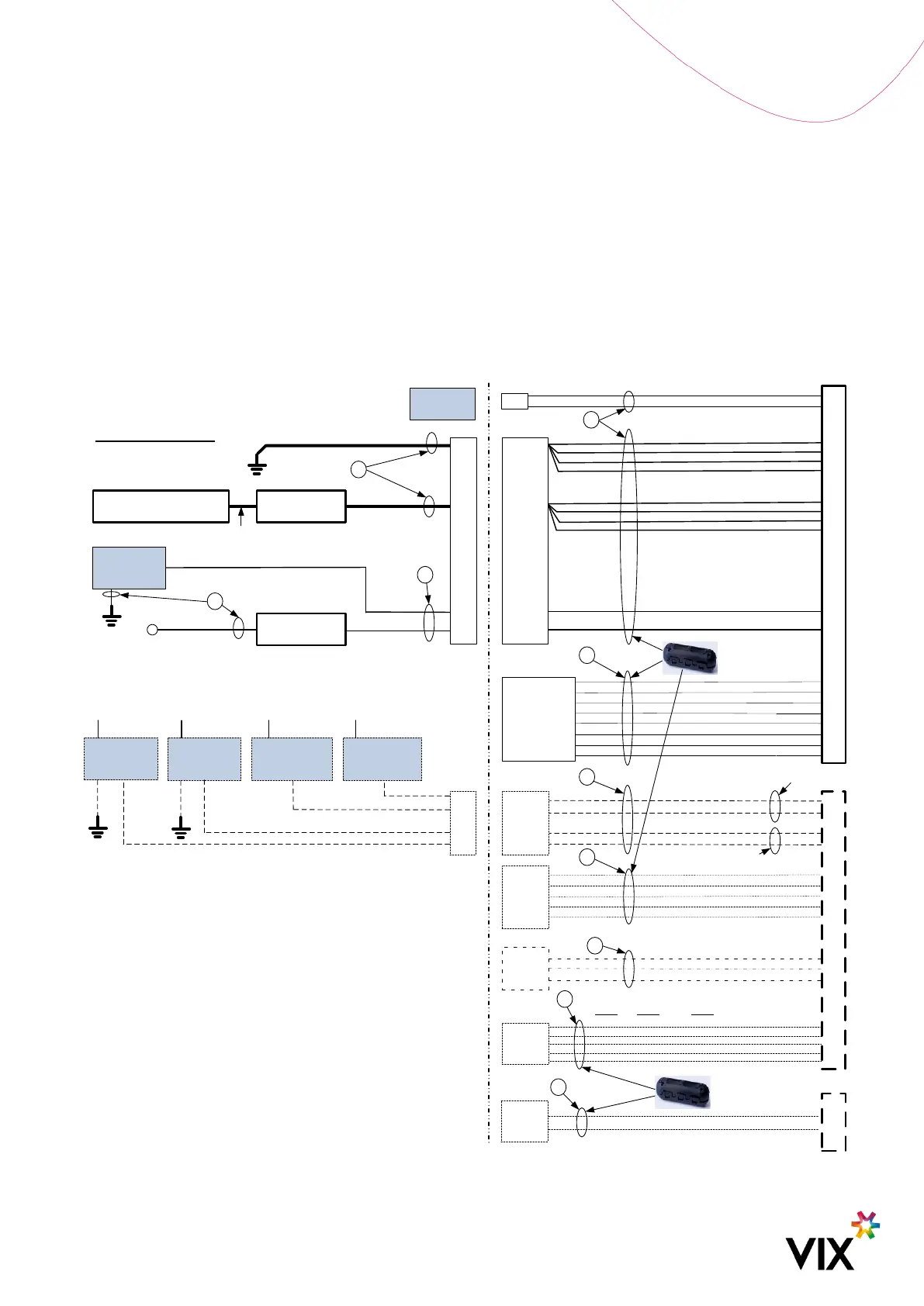
The following drawing shows an Adept Validator installed in isolation, with only general reference to external
devices.
The example diagram is mainly for the Adept Validator end only, any interconnection and extension between the
Adept Validator and the terminal end needs to be discussed and confirmed between the customer and VIX.
IGNITION
CIRCUIT BREAKER OR
POWER TERMINAL
CURRENT RATING >
CIRCUIT BREAKER OR
UPSTREAM FUSE
*
GROUND STAR POINT
(CONNECT ALL TRANSIT
SYSTEM DEVICES TO THIS
COMMON GROUND POINT)
>2.9A RATED
>2.9A RATED
>1.5A RATED
BATT+
BATT_GND
REMOTE_ONOFF_L
EXT_IN_GPO_1
1-WIRE_GND
1-WIRE
USB_OTG_P
USB_OTG_ID
USB_OTG_N
USB_GND
MDI_0_P
MDI_3_N
MDI_0_N
MDI_3_P
C
1-Wire Assembly
CBL0429
RS232-Diag_ Rx
RS232-Diag_Gnd
RS232-Diag_Tx
RS232
Diag
B
Keep USB+/- Twisted (90ohm) & < 2m
E
Turnstile or other
relay operated device
VBAT+
A
VBAT+
RS422_TX-
RS422_RX+
RS422_RX-
RS422_TX+
NU
F
D
1
19
20
21
22
15
17
18
19
20
TX232_CH2
RX232_CH1
RX232_CH2
TX232_CH1
RS232_GND
RS485-
NU
NU
RS485+
NU
1
2
12
14
16
7
8
9
10
13
REMOTE_ONOFF_H
/ IGNITION
14
5
9
MDI_1_P
MDI_2_N
MDI_1_N
MDI_2_P
23
24
25
26
Connector 1
11
VBUS_OTG
2 x RS-232
or 1 x RS-
485 or 1 x
RS-422
EXT_IN_GPO_2
2
Turnstile or other
relay operated device
General purpose
digital signal
VBAT+
General purpose
digital signal
VBAT+
5
6
EXT_IN_H_1
EXT_IN_H_2
6
10
A
>1.5A RATED
VBAT+
10/100/1000 BaseT
Ethernet
USB OTG
Connector
2 (Optional)
GPIOs
Conn to mate
/
Interconnection
1A CIRCUIT
BREAKER
A
>1.5A RATED
Remote On/Off Low
Control Line
GND for ON
2A CIRCUIT
BREAKER
A
Conn
Relay Output (Switched to VBAT+
or BAT_GND configurable)
Input Active High
TXCVR_A_B_P
TXCVR_GND
TXCVR_A_B_N
TXCVR_Y_Z_P
TXCVR_Y_Z_N
RS485
RS232 RS422
BATT_GND
BATT+
Diagnostics is most likely not
required for normal installation
Alternative option to the
Remote ON/OFF High
Conn to mate
/ Interconnection
BATT_GND
7
8
BATT_GND
BATT+
11
12
BATT+
Power +
Ignition
Conn
3
(Optional)
GPS
GPS
GPS_GND
Centre
Shield
G
One per loom
One per loom