Refer to section 5.2 for the connectors and crimps to be used at the Adept Validator end. Refer to sections 5.3 and
5.4 for recommendation on circuit breakers and cables.
Note: The above diagram is for a 24V bus system, with 0 to 20-meter power cable and 70% derating of
cable’s maximum current rating. Refer to section 5.5 for information on the power cable selection.
Caution: For any connected signal group (power, Ethernet, USB, multiprotocol or GPS), a ferrite MUST be
used on the cable on the Adept Validator end to ensure EMC performance. The recommendation is
Laird Technologies # 28A0593-0A2 (shown in the above diagram), but any ferrite with similar
impedance characteristics and size could be submitted to VIX for approving its use.
Note: The ferrites could be offset in position to accommodate for the space constraint within the pole.
They should be secured in place on its cable group with cable ties or other means. They need to be
installed prior to cradle mounting as it is difficult to position/fit them through the pole/cradle.
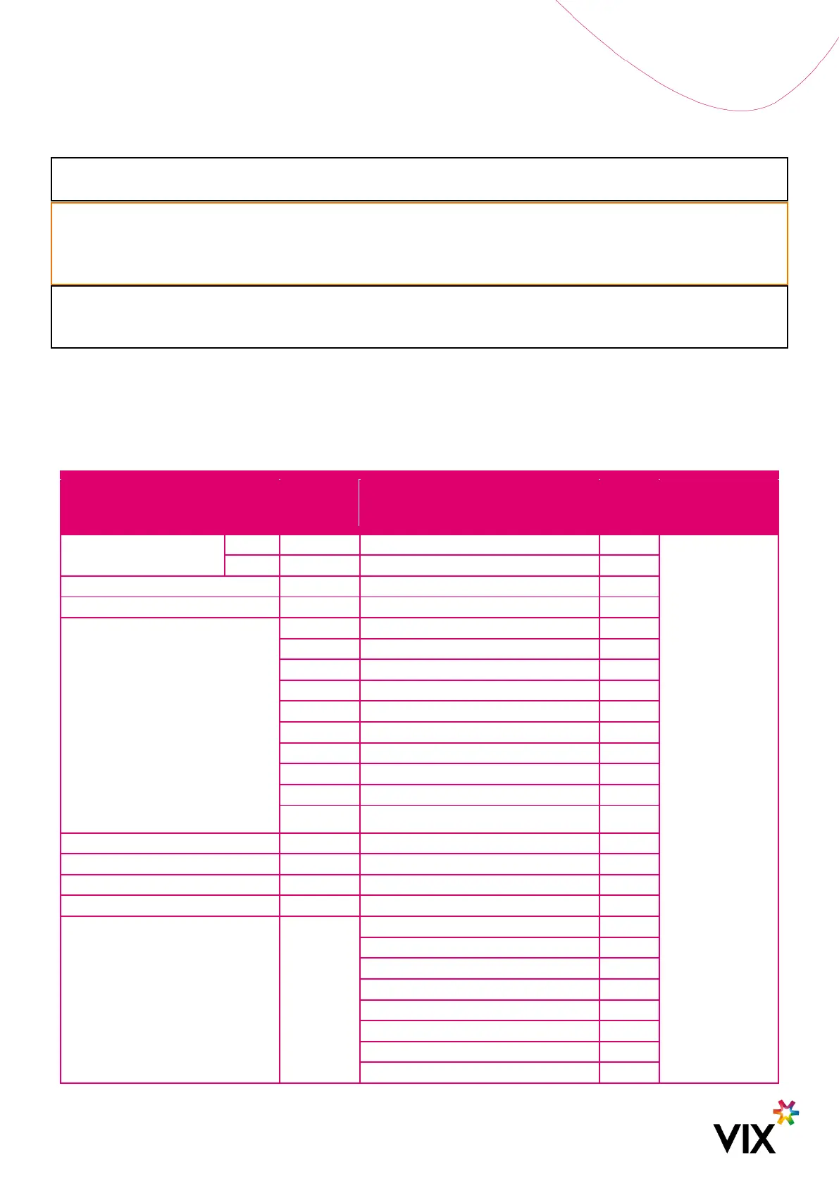
Interconnection connectors are recommended to be used between the validator end and the end terminal/device.
This provides flexibility in installation and removal. The below table presents the above wiring in a table format with
the interconnection recommendations, but they could be altered, based on the actual application/requirement.
Table 4: Cable Connection Mapping
Interconnection (suitable for wire
gauges on both sides), then:
Power: Cable B => BATT_GND
to Ground star point, and
BATT+ to 2A circuit breaker
Control: Pin13 to External low
control line AND Pin 14 to 1A
circuit breaker then external
high control line