IVTM
3
System Description
IVTM with TEBS D, TEBS E or TCE
Installation in a vehicle with TEBS D, TEBS E or TCE is simple because this
merely has to be plugged into pre-assembled cables. Other systems would require
open wiring that needs to be enclosed by protective housing.
Observe the current installation instructions for the control unit of the ABS / EBS in
the WABCO product database INFORM http://www.wabco-auto.com
and / or those
of the vehicle manufacturer.
The circuit diagrams illustrated in the following table in excerpt form can be re-
trieved from INFORM.
Wiring diagrams for trailers
The circuit diagrams shown in excerpt form below can be retrieved from the
WABCO online product database NFORM at http://www.wabco-auto.com
. To re-
trieve them, enter the desired circuit diagram number in the "Product number" input
field.
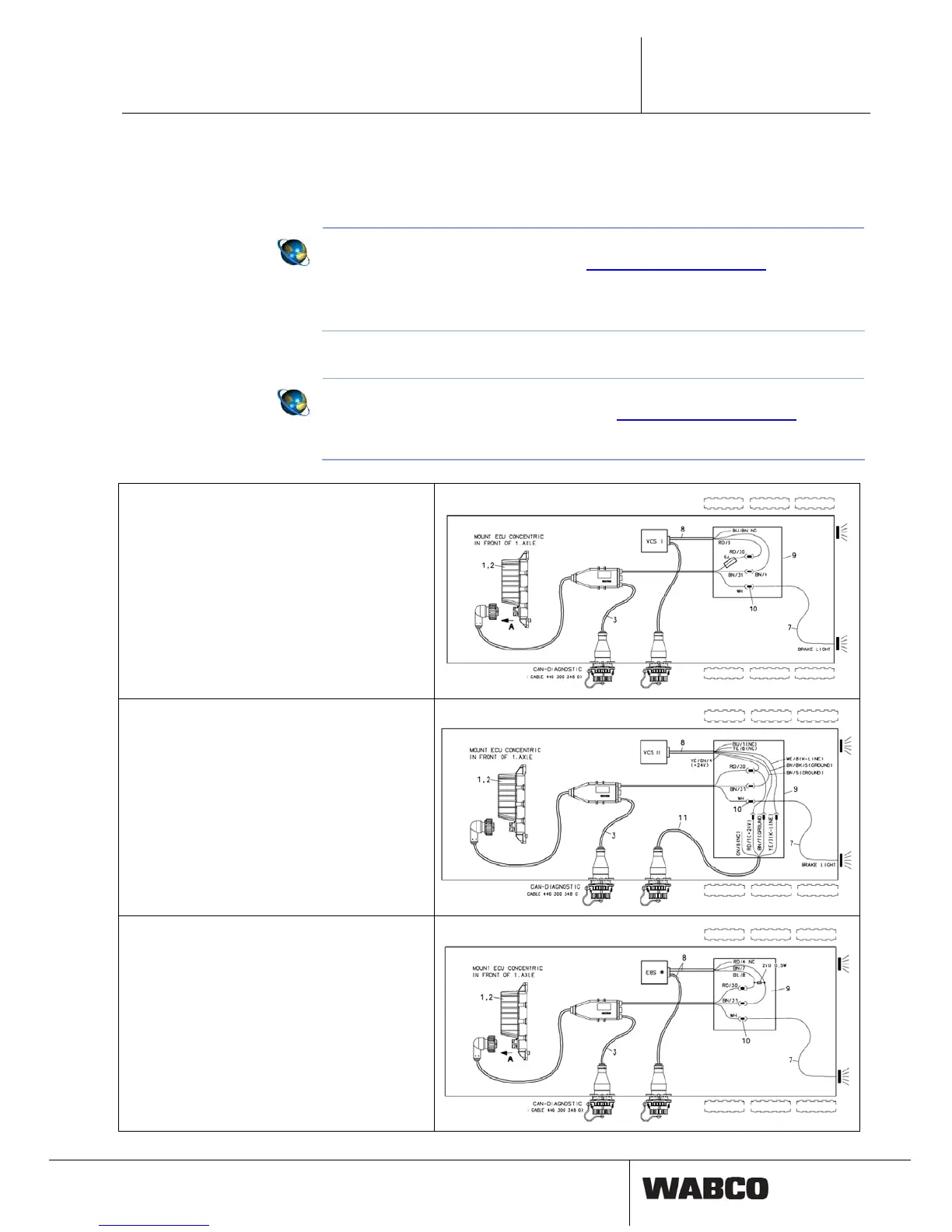
Wiring diagram 841 801 943 0:
Trailer ABS VCS
Cable position 8 (449 314 ... .) is opened and con-
nected to cable position 3 (449 674 273 0) and a
line to the stop light in a wiring box.
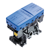
Wiring diagram 841 801 946 0:
Trailer ABS VCS II
Cable position 8 (449 336 ... .) is opened and con-
nected to cable position 3 (449 674 273 0), cable
position 11 (449 621 ... .) and a line to the stop light
in a wiring box.
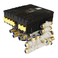
Wiring diagram 841 801 941 0:
Trailer EBS with CAN connection
Cable position 8 (449 614 ... .) is opened and con-
nected to cable position 3 (449 674 273 0) and a
line to the stop light in a wiring box. The ISS output
must not be used and needs to be set to 0 km/h.
13