3
IVTM
System Description
14
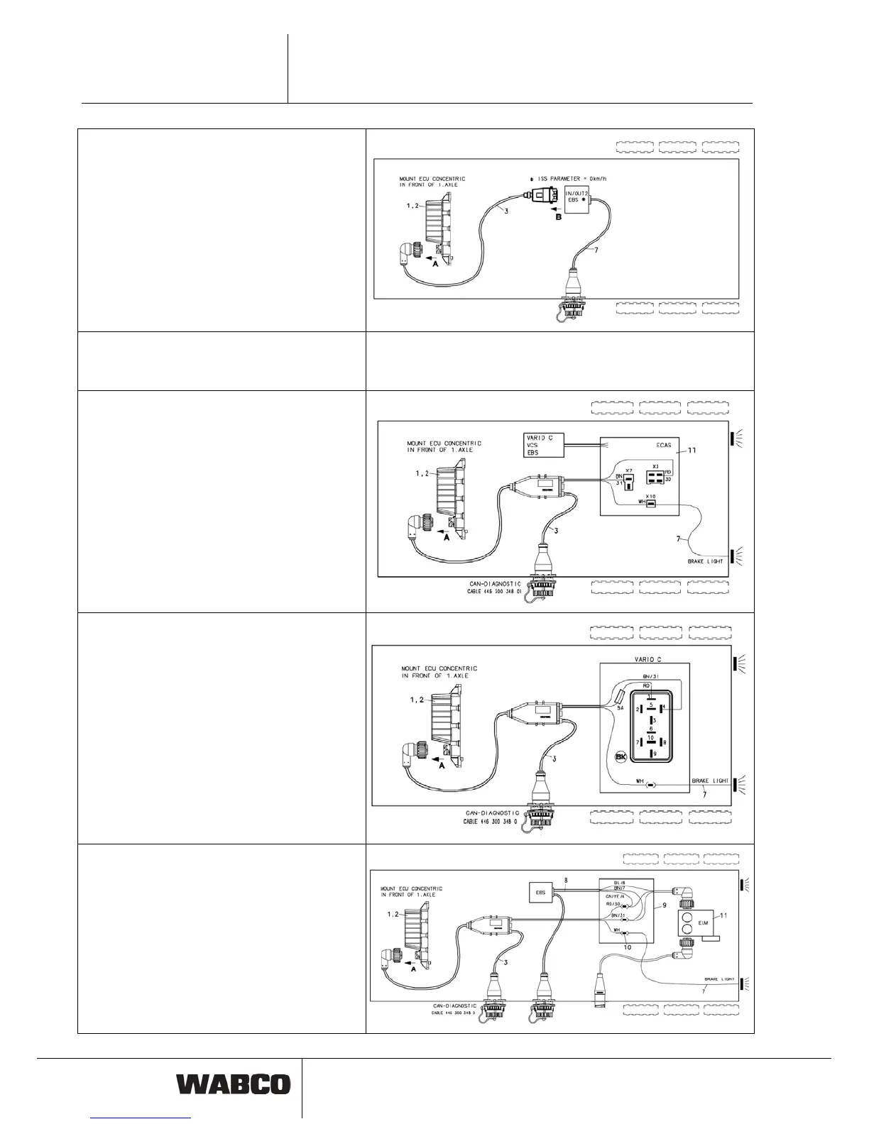
Wiring diagram 841 801 945 0:
Trailer EBS D with CAN
Connection is made with cable position 3
(449 377 ... 0 / 449 378 ... 0). The ISS output must
not be used and needs to be set to 0 km/h. IVTM
diagnosis through diagnostic cable 446 300 329 2
via TEBS diagnostic port.
Trailer TCE
Connection like on Trailer EBS D with CAN but with
cable 449 302 ... 0.
Wiring like 841 801 945 0
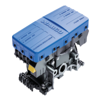
Wiring diagram 841 801 940 0:
Trailer ECAS
Cable position 3 (449 674 273 0) is introduced into
bottom box of ECAS-ECU and connected there.
One cable to stop light (position 7) is installed addi-
tionally. You need screwed cable glands (PG 11:
894 130 312 2) for two cables.
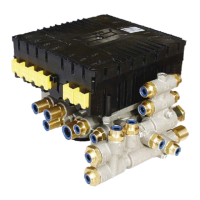
Wiring diagram 841 801 944 0:
Vario-C
Cable position 3 (449 674 273 0) is introduced into
bottom box of ABS-ECU and connected there. One
cable to stop light (position 7) is installed addition-
ally. You need screwed cable glands (PG 11:
894 130 312 2) for two cables.
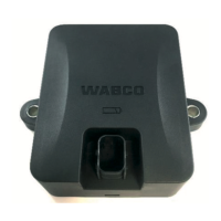
Wiring diagram 841 801 942 0:
Trailer EBS and ELM
Cable position 8 (449 344 ... .) is opened and con-
nected to cable position 3 (449 674 273 0) and a
line to the stop light in a wiring box.