4
IVTM
Components
22
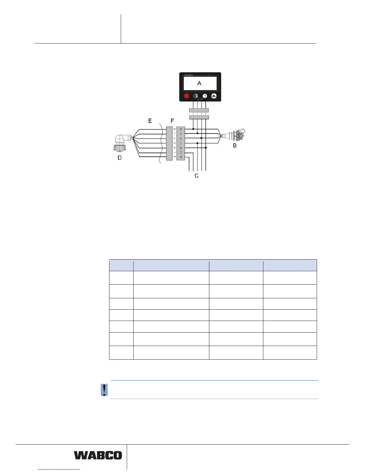
Basic wiring principle for towing vehicle / bus is displayed in the following illustra-
tion.
fig. 4-7: Wiring of towing vehicle
A
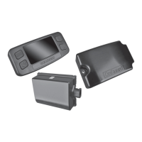
Display
B
Diagnosis
C
Vehicle electric system
D
ECU
E
external
F
inside
Pin No. Connector pin assignment Cable colour 5-pin Cable colour 7-pin
6 CAN High
1 CAN Low
3 GND blue blue
7 +24 V or 12 V red red
5 Ignition amber & grey grey
2 Stop light / warning lamp 2
amber
4 Warning lamp 1
green
Table: 4-2: Cable set assignment
Connection to +12 V/24 V and ignition to be fused through 5 ampere fuses. Since
IVTM has low current consumption an existing fused circuit can be used.