IVTM
4
Components
23
Cable set towing vehicle, 7-p
The 7-pin wiring is implemented to match cable set 894 607 390 0, see figure 4-7
"Wiring of towing vehicle", page 22. Pin assignment on the connecting plugs corre-
sponds
to the 5-pin variant. In addition, either connection to stop light (for synchro-
nising with trailer ECU) and warning lamp or connection of two warning lamps is
possible.
Cable set towing vehicle, 5-pin
Simpler wiring is intended as 5-pin variant for bus retrofitting: 894 607 295 0. Em-
ployment of this wiring allows driving of warning lamps inside display or via CAN
respectively but not separate warning lamps on dashboard.
Cable set, trailer
Information about the different interconnections with CAN-enables systems (with
TEBS or TCE), see chapter 3.3 "Configuration for bus and towing vehicle", page 10
and see chap
ter 3.4 "Configuration for trailers ", page 12.
Cabl
e set 449 674 273 0 should b
e used if data transmission is made through wire-
less connection only, see figure 4-8 "Trailer wiring", page 23.
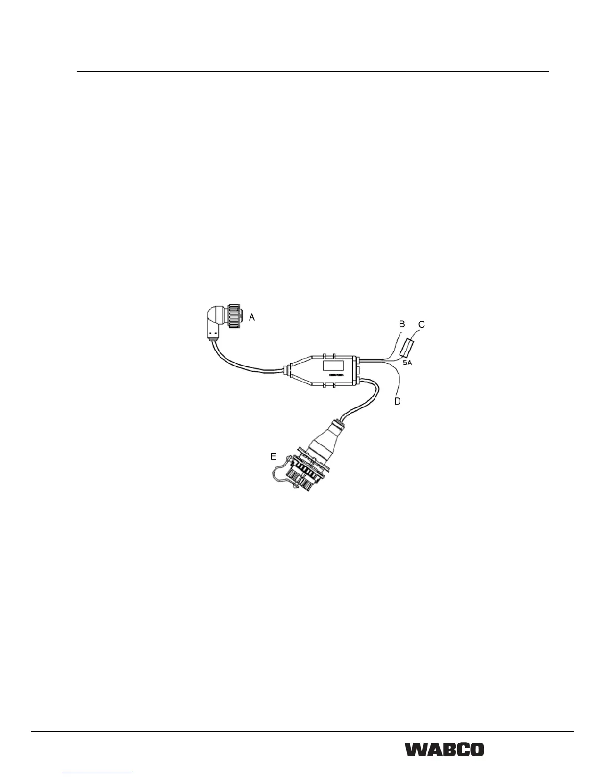
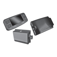
in
fig. 4-8: wiring Trailer
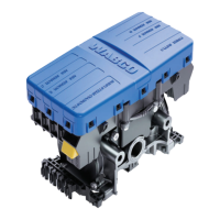
A
ECU
B
Brown: Ground
C
Red: +12 V/24 V
D
White: Stop light
E
Diagn
Diagnostic cable
Cable 446 300 348 0 connects diagnostic connector on vehicle with Diagnostic In-
osis
terface during diagnosis. More information on the subject of "Diagnosis" see chap-
ter 7.1 "Diagnosis", page 40.