TEBS E
11
Workshop notes
185
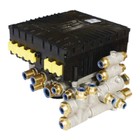
11.3 Diagnostic Hardware
The TEBS E only enables diagnosis via one of the CAN interfaces, see following
options.
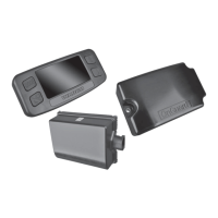
The CAN interface conforming to ISO 11898 can be used connecting SUBSYS-
TEMS e.g. IVTM, Telematics, SmartBoard or ELEX.
For further information please refer to the document ‘Diagnosis – Soft-
ware/Hardware’, see chapter 4 ‘Introduction’, page 12 => Se
ction ‘Further informa-
tion’.
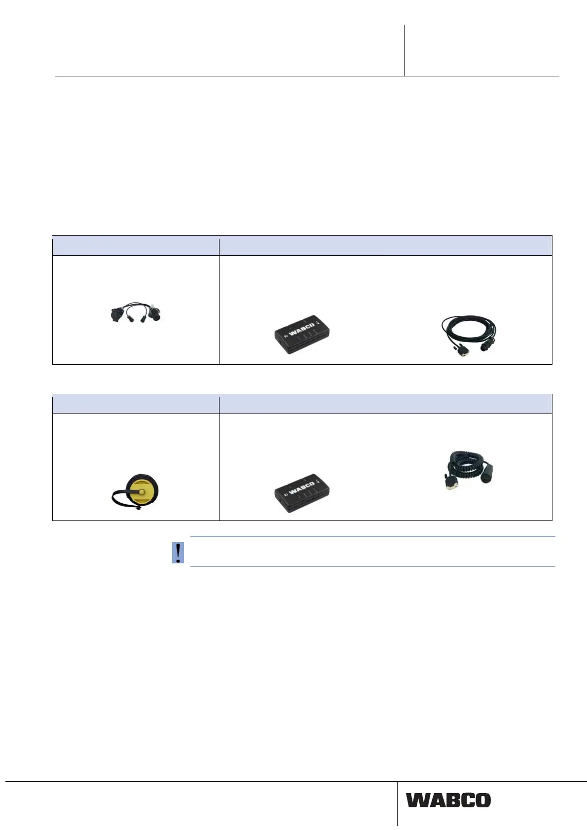
Option 1 - diagnosis conforming to ISO 11992 (CAN 24 V); via the 7-pin ISO 7638 CAN connection
Requirements Diagnostic Hardware
ISO 7638 disconnecting adapter with
CAN plug-in socket
446 300 360 0
Diagnostic Interface (DI-2)
with USB port
(for connection to PC)
446 301 030 0
CAN diagnostic cable
446 300 361 0 (5 m)
or
446 300 362 0 (20 m)
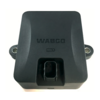
Option 2 - Diagnosis according to ISO 11898 (CAN 5 V): via an external diagnosis connection
Requirements Diagnostic Hardware
External diagnostic socket with yellow
cap
Only TEBS E Modulators (Premium)
449 611 ... 0
Diagnostic Interface (DI-2)
with USB port
(for connection to PC)
446 301 030 0
CAN diagnostic cable
446 300 348 0
Do not use the USB interface with 5 V CAN-Bus converter.
Diagnosis
A system diagnosis must be carried out every time anything unusual is noticed in
the system or a warning lamp / fault indicator lights up.
Currently faults as well as intermittent ones are stored in the TEBS E diagnostic
memory and displayed via the TEBS E Diagnostic Software. The Diagnostic Soft-
ware provides instructions for a repair.
Once a fault has been eliminated, the diagnostic memory should always be cleared.