TEBS E
12
Appendix
195
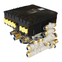
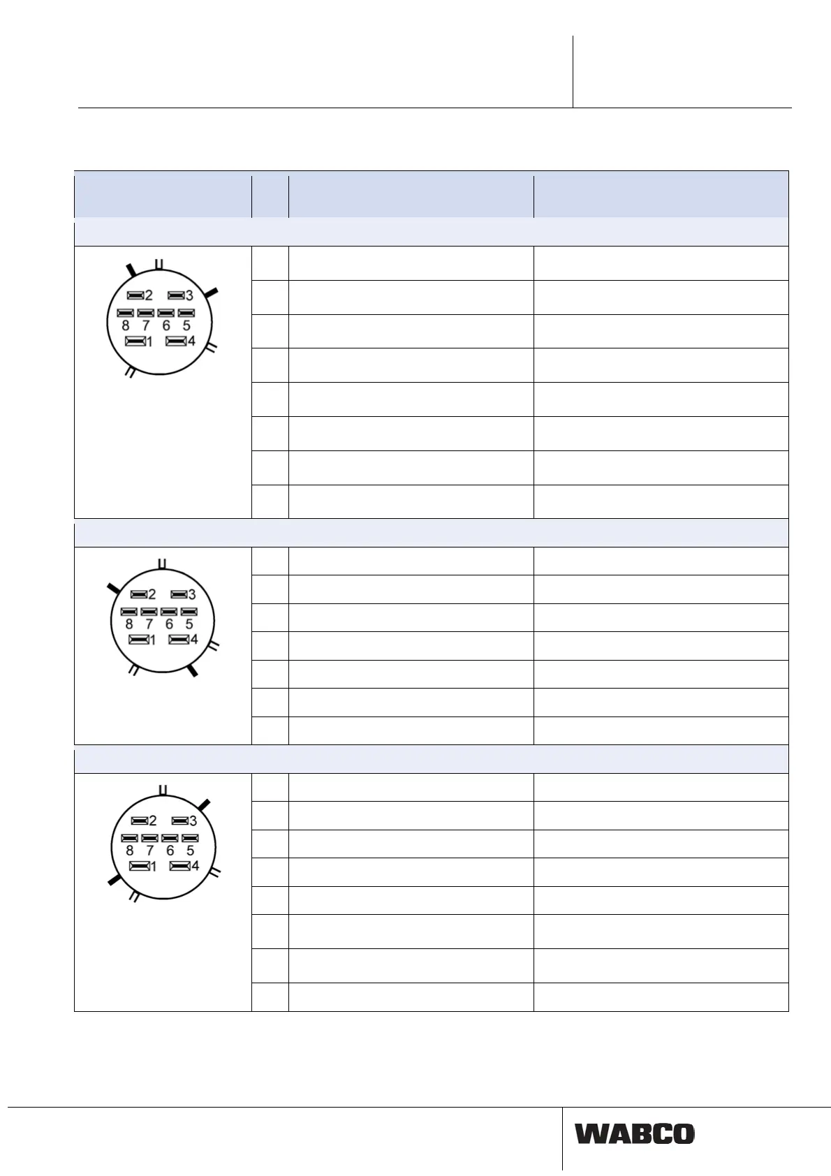
12.2 Pin assignment TEBS E Modulators and ELEX
Connections Pin TEBS E Modulator
(Standard)
TEBS E Modulator
(Premium & Multi-Voltage)
MODULATOR, 8-pin Code B, Grey
1
Ground ‘Input/Outlet valve’
2
Backup valve
3
Ground ‘Backup valve’
4
Ground ‘Pressure sensor’
5
+24 V/Supply ‘Pressure sensor’
6
Actual pressure
7
Outlet valve
8
Inlet valve
POWER, 8-pin Code A, Black
1 Steady positive voltage / Terminal 30 Steady positive voltage / Terminal 30
2 Ignition / Terminal 15 Ignition / Terminal 15
3 Ground ‘fault indicator / warning lamp’ Ground ‘fault indicator / warning lamp’
4 Ground ‘Valves’ Ground ‘Valves’
5 Fault indicator / warning lamp Fault indicator / warning lamp
6 CAN-High 24 V CAN-High 24 V
7 CAN-Low 24 V CAN-Low 24 V
SUBSYSTEM, 8-pin Code C, Blue
1 Steady positive voltage / Terminal 30 Steady positive voltage / Terminal 30
2 CAN2-High 5 V CAN2-High 5 V
3 CAN2-Low 5 V CAN2-Low 5 V
4 Ground Ground
5 GIO power stage 4-2 GIO power stage 4-2
6
Control element Clock
7
Control element Data
8 ABS rotational-speed sensor c ABS rotational-speed sensor c