RD 12/RD 12A Schematics
wc_tx001073gb.fm 121
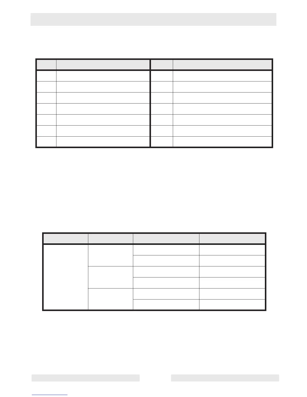
10.2 Hydraulic Schematic Components
10.3 Electrical Schematic Identification—RD 12A
Use the chart below to determine which electrical schematic applies to
your machine.
Ref. Description Ref. Description
1 Steering cylinder 8 Return filter
2 Steering unit 9 Tank
3 Drive motor 10 Suction strainer
4 Bypass lever 11 Vibration solenoid valve
5 Charge pump 12 Exciter motor
6 Main pump 13 Pressure relief valve
7 Exciter pump - ---
Roller Item No. Revisions
Electrical Schematic
RD 12A 0620058 111 & higher B
110 & lower A
0620320 109 & higher B
108 & lower A
0620369 111 & higher B
110 & lower A