RD 12 / RD 12A Vibration System and Steering
wc_tx000668gb.fm 61
6.4 Checking the Vibration Switch
Background When the roller’s engine is running, the solenoid of the vibration manifold receives
power through the white wire via the vibration switch. To check the function of the
vibration electrical system, both the vibration solenoid and the vibration switch
should be tested.
Procedure Follow the procedure below to check the vibration switch.
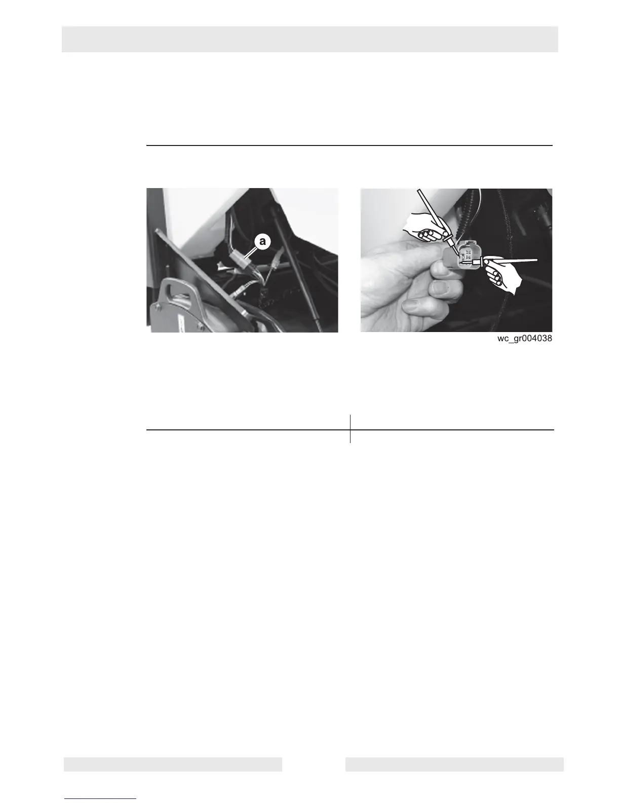
1. Remove the four screws that secure the seat platform. Then, raise the platform.
2. Locate the connector (a) for the vibration switch and disconnect it.
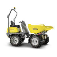
3. Press the switch several times while checking for continuity between the pins of
the connector (two black wires).
Does the switch open and close
4. Reconnect the wiring.
The vibraton switch has now been checked.
Yes ____ No ____
The vibration switch is OK. The vibration switch has failed; replace it.