RD 12/RD 12A Disassembly & Assembly
wc_tx000671gb.fm 99
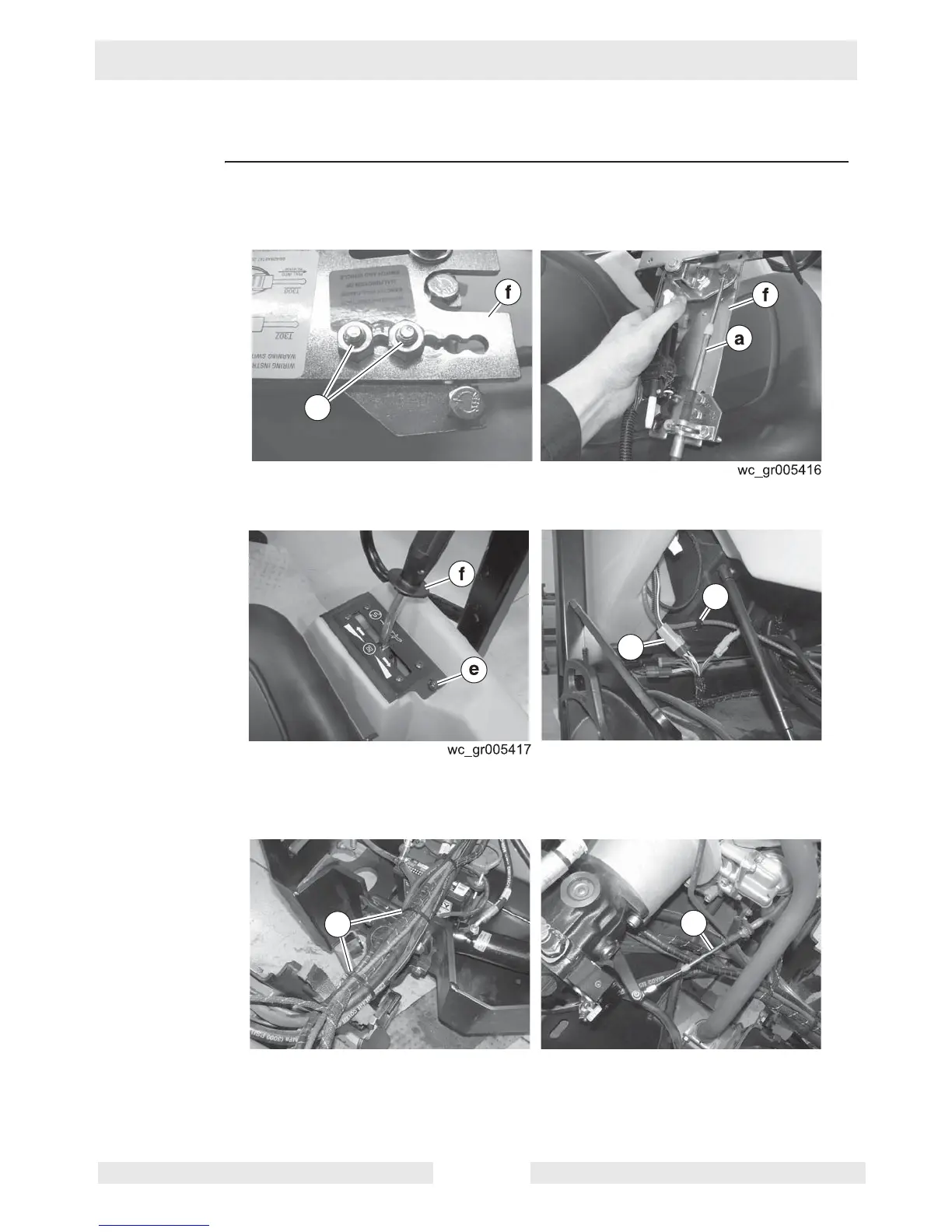
9.22 Installing the Control Cable and Control Lever
Prerequisites Seat platform in raised position
Procedure Follow the procedure below to install the control cable and the control lever.
1. Check that the clamp bracket is positioned correctly. It should be positioned with the
screws (g) in the first and third holes of the control lever assembly (f).
2. Connect the control cable (a) to the control lever assembly (f).
3. Install control lever assembly (f) with the screws (e)
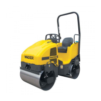
4. Install the cable clamp (d).
5. Connect the wiring at the connector (c).
6. Secure the hoses, wires, and cables with new wire ties (b).
7. Maneuver the control cable (a) around the engine and connect it to the drive pump.
The procedure to install the control cable and the control lever is now complete.
g
wc_gr004190
c
d
wc_gr004193
a
b