Spray System RD 12/RD 16
wc_tx000670gb.fm 66
8.3 Checking the Pump Timer Module
Background
The pump timer module is fed power in two locations:
Via key switch on pink wire #01
Via spray system switch on pink wire #18
Procedure
Follow the procedure below to check power to the pump timer module.
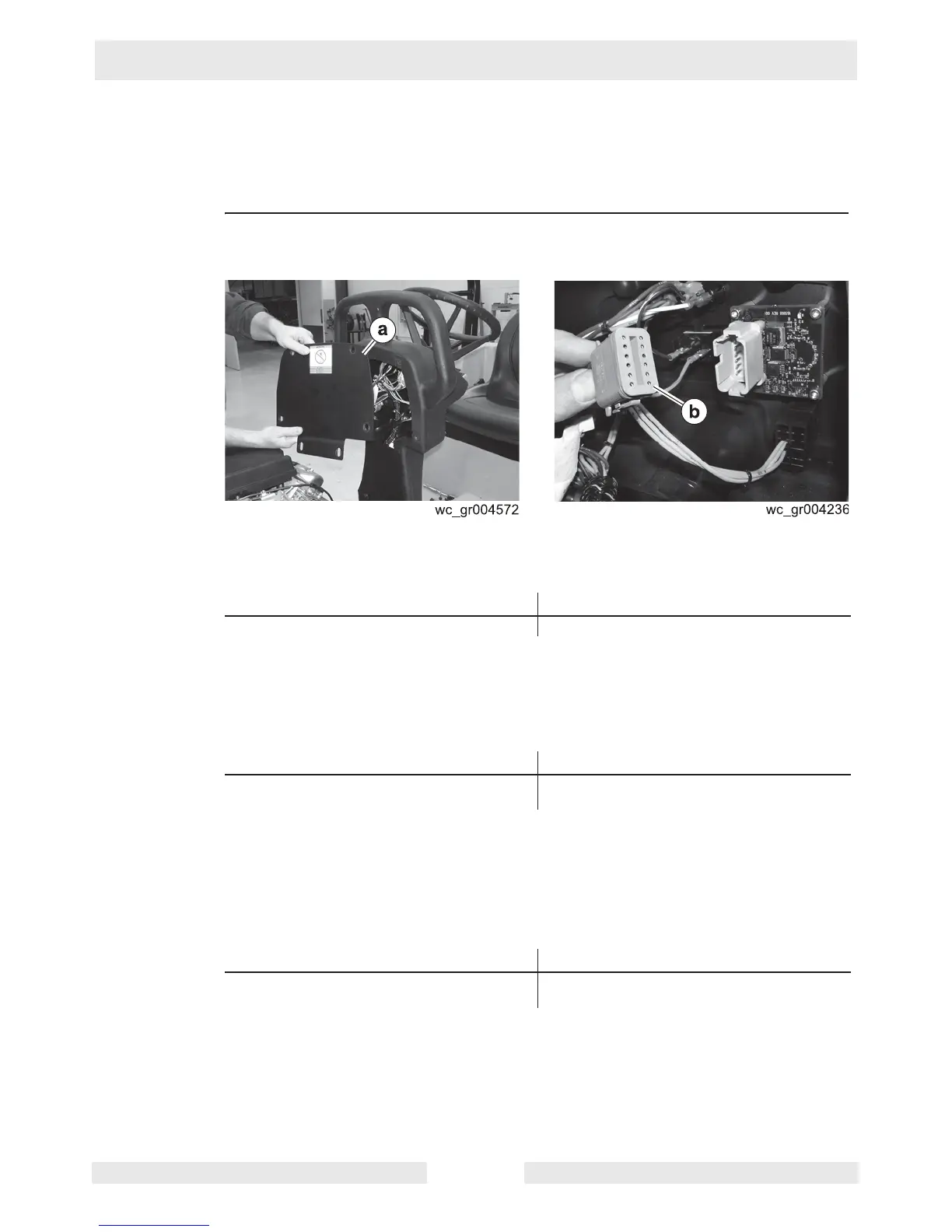
1. Remove the control console cover (a).
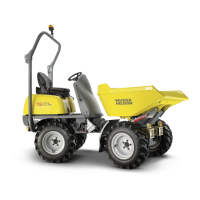
2. Disconnect the pump timer module connector (b).
3. Measure the voltage between pink wire #01 (connector pin 1) and ground.
Is more than 9.8V measured?
4. Place the key switch in the ON position.
5. Place the spray system switch in the ON position.
6. Measure the voltage between pink wire #18 (connector pin 11) and ground.
Is more than 9.8V measured?
7. Reconnect the pump timer module connector.
8. Measure the voltage between pink wire #18 (backprobe connector pin 6) and
ground.
Note:
The voltage will be intermittent depending on the setting of the pump timer dial.
Is more than 9.8V measured
?
9. Re-install the control console cover.
The pump timer module has now been checked.
Yes ____ No ____
Continue Repair or replace pink wire #1.
Yes ____ No ____
The pump timer module is receiving power
and should be working; continue.
Repair or replace pink wire #18.
Yes ____ No ____
The pump timer module is functioning. The pump timer module has failed;
replace it.