RD 12/RD 16 Spray System
wc_tx000670gb.fm 67
8.4 Checking the Spray System Switch
Background The spray system switch is fed power via the key switch on pink wire #29. When in the ON
position, the spray system switch allows power to the pump control timer via pink wire #18.
Procedure Follow the procedure below to check the spray system switch.
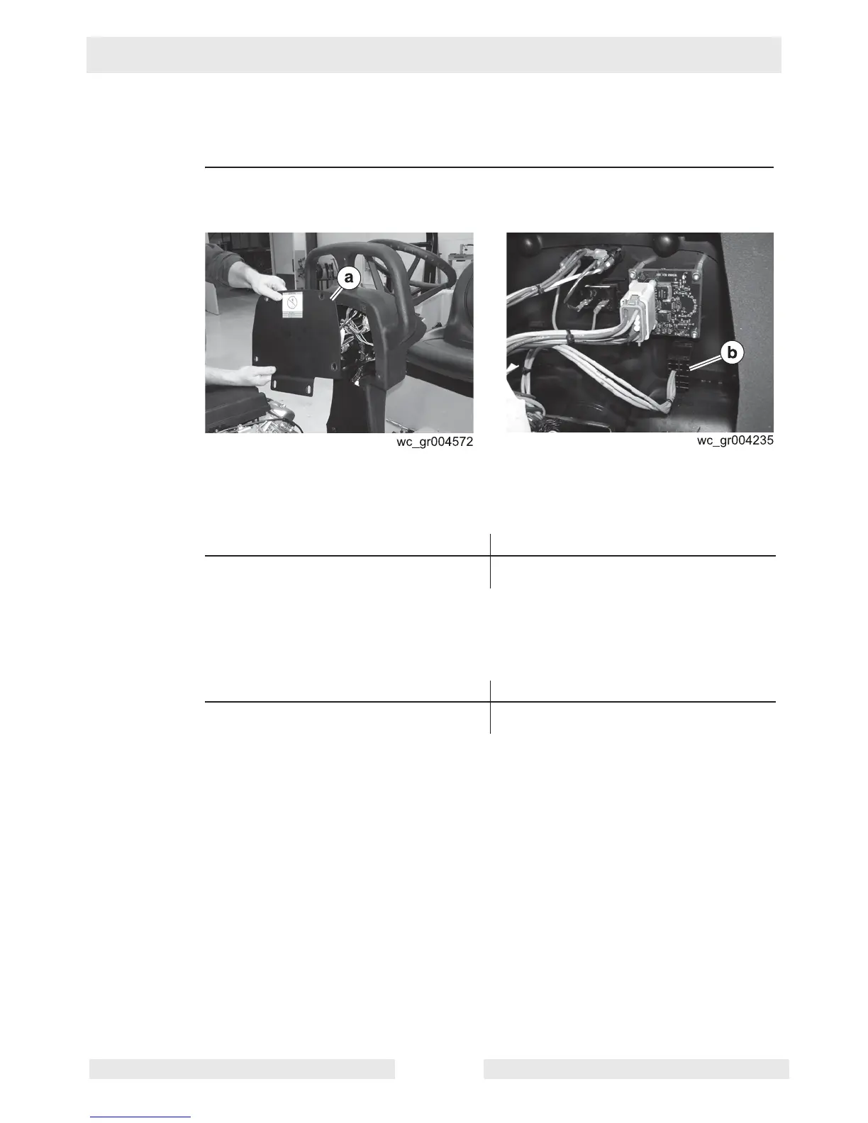
1. Remove the control console cover
(a).
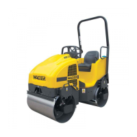
2. Place the key switch in the ON position.
3. Measure the voltage between the incoming side of the spray system switch (b)
(pink wire #29) and ground.
Is more than 9.8V measured?
4. Place the spray system switch in the ON position.
5. Measure the voltage between the outgoing side of the spray system switch (pink
wire #18) and ground.
Is more than 9.8V measured?
The spray system switch has now been checked.
Yes ____ No ____
Continue Check the continuity of pink wire #29.
Repair or replace pink wire #29.
Yes ____ No ____
The spray system switch is
functioning.
The spray system switch has failed;
replace it.