5-18 BA ET18, 20, 24 en* 1.5 * et18_20_24b510.fm
5 Operation
Hydraulic swivel unit brake:
The upper carriage’s rotation is sufficiently braked by moving the control
lever on the left back to initial position. Moving the control lever in the
opposite direction (counteraction) brakes the upper carriage with
maximum hydraulic output.
Mechanical swivel unit brake:
A multidisk brake integrated in the rotation drive has an additional
mechanical brake effect. The brake is used for braking the swivel unit. The
upper carriage can be stopped in any position.
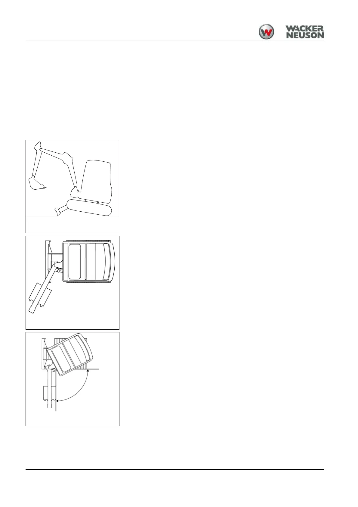
Functional check of swivel unit brake
1. After finishing work, park the machine at operating temperature on
firm, level, and horizontal ground.
2. Raise the machine with the stabilizer blade as far as it will go.
3. Swivel the boom to the left as far as it will go.
4. Turn the upper carriage so that the boom is 90° to the travel gear.
Fig. 139 Raising the machine
Fig. 140Swivel boom to the left
Fig. 141Boom 90° to the machine
90°
 Loading...