Operation
Instruments and operating elements
62
BA RD24_RD28 en us 06
310
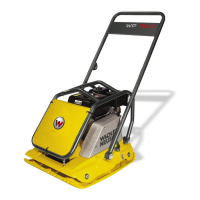
Electrical system / engine start
The switch (ignition key) supplies the electrical components with power,
and starts and stops the diesel engine.
0-position
Electrical system — OFF
Diesel engine — STOP
(key released)
Position I
Electrical system — ON
Position II — PREHEAT
Position III — ENGINE START
Key turns back to position I after starting.
NOTE
When the engine is at a standstill and the electrical system
is switched on for a longer period (position I), the battery
discharges rapidly.
000-28
NOTE
The machine may not be operated for safety reasons when an
attempt is made to start the diesel engine while the emergency
stop button is pressed.
To activate the machine:
1. Latch drive lever [501] in 0 position.
2. Release EMERGENCY STOP switch [302].
311
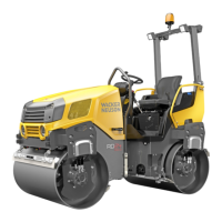
Rotating light
Pressing the switch turns the rotating light on or off.
On — PRESS
(pilot light lights)
Off — PRESS again
312
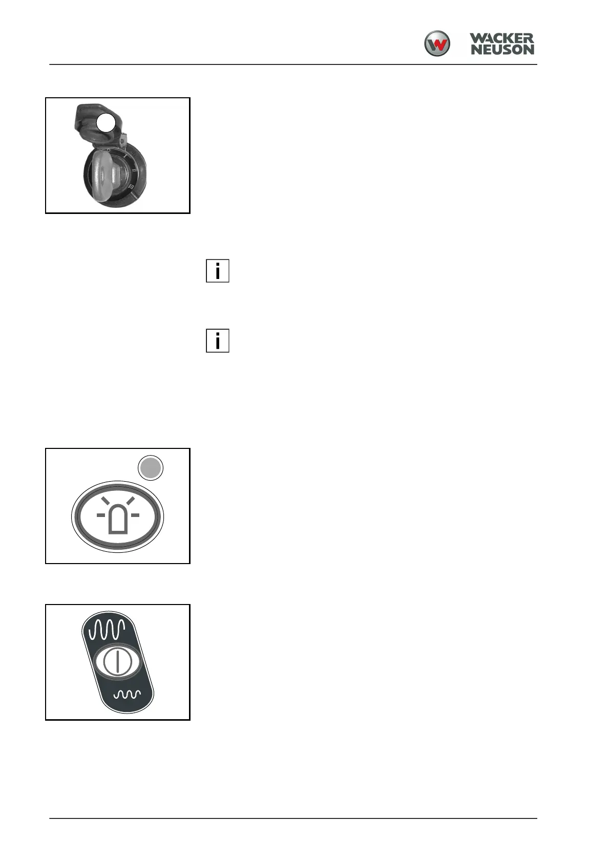
Vibration / Oscillation
Pressing the switch activates or deactivates the vibration / oscillation
system. Each actuation of the switch switches one step ahead.
Activation — PRESS
(pilot light [222] lights up)
Deactivation — PRESS again
(pilot light [231] lights up)
When the vibration / oscillation system is activated, the vibrator / oscillator
can be switched on or off at the multifunctional handle [503].