24
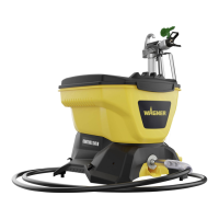
Control 150 M
GB
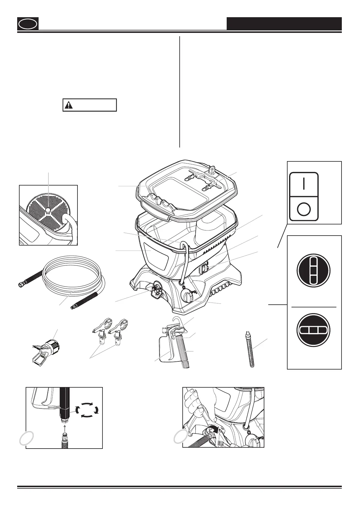
Components
•
Spray gun with lter
•
Spray tip assembly
•
7.5 mtr. long
Tools needed for assembly
•
Two adjustable wrenches.
WARNING
Do not plug in the unit until setup is complete.
Controls and functions
ON/OFF switch The ON/OFF switch turns the unit
on and o (O = OFF, l = ON)
Spray Gun The spray gun controls the
delivery of the uid being
pumped.
Spray Hose The spray hose connects the gun
to the pump.
Return Tube Fluid is sent back out through the
return tube to the hopper when
priming.
PRIME/SPRAY knob The PRIME/SPRAY knob directs
uid to the spray hose when set
to SPRAY, or the return tube when
set to PRIME.
= ON
Assembly
1
2
Place the spray gun against the tapered end of the hose
and twist the gun onto the hose. Firmly tighten the
thread using a wrench
Twist the thread at the other end of the hose onto the hose
connection. Using a wrench, hold the hose connection rmly and
tighten the hose with another wrench.
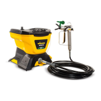
COMPONENTS AND ASSEMBLY
Motor
housing
ON/OFF
switch
PRIME/SPRAY knob
Trigger lock
Trigger
Return tube
Outlet valve
Tip storage
Spray gun
Hopper lid
Hopper
Tip guard
Tip
Filter (white)
preassembled
in gun
Handle
Spray hose
Inlet lter
(inside of hopper)
Filter (red)
PRIME/SPRAY
knob
PRIME
Position
SPRAY
Position