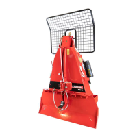
Transport
FX85, FX110, FX140
Skidding Winch
38
7.4 Size a PTO Shaft
WARNING!
Avoid the risk of personal injury or machine
damage! Read the operator’s manual before
using the equipment. Carefully read all safety
messages in the manual and follow all safety
labels on the machine.
CAUTION!
Wear the correct eye protection when you cut a
steel tube.
IMPORTANT! It can be necessary for the PTO shaft that
came with your machine to be cut shorter. A longer shaft is
supplied because tractor lift arms have different lengths.
The PTO shaft must be able to telescope and not reach its
limit (bottom out) when it moves through the working range.
The PTO shaft should never fully collapse in use. There
should always be a minimum of 2" (50 mm) available for the
PTO shaft to retract.
If the PTO shaft gets to the limit, the bearings on each end
can overload and fail causing damage or injury.
IMPORTANT! Using a drive shaft that was not supplied with
your machine can result in it being assembled out of phase
(the universal joint yokes are not aligned with each other).
Make sure that the drive shaft is assembled with the u-joints
in phase. If the u-joints are out of phase, the unbalances can
cause wear and eventually the drive shaft will fail.
IMPORTANT! The two PTO shaft halves should overlap
inside at a minimum of 6" (150 mm).
1. Remove the PTO shaft from the machine.
2. Attach the machine to the tractor three-point hitch.
For instructions, see Attach to a Tractor on page 34.
3. Start the tractor.
4. Raise the three-point hitch off the ground until the
machine's input shaft is level with the tractor's PTO output
shaft.
This is the shortest distance between the input and
output shafts.
5. Disengage the tractor PTO.
6. Apply the tractor parking brake.
7. Stop the tractor engine and remove the ignition key.
8. Wait for the PTO shaft to stop.
9. Separate the PTO shaft into two sections.
10. Put one section of the PTO shaft on the tractor output
shaft, and put the other section on the machine input shaft.
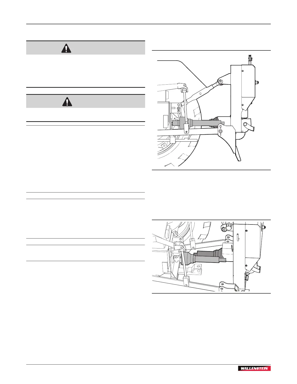
Figure 37 – PTO shaft on the input shaft and output shaft
11. Lift the ends of the PTO shaft until they are as parallel to
each other as possible. Support the PTO shafts with blocks
or tie them together.
If the PTO shafts are too long or there is not enough room,
see, Alternate Method on page 40.
Figure 38 – Lift the PTO shafts until they are parallel