5.0 INSTALLATION AND FIXING
2
FIL.SILOTOP_zero.--.M.A4.0722.EN Issue: A4
07.22
22
The compressed air must be:
1) Clean: with no residues that might damage the lter.
Danger - Warning
Drain the piping prior to connecting the compressed air to the lter.
2) De-moist- The air tank is provided with a condensate drainage tap. The user should provide for a conden-
sation separator.
3) Oil-free -The presence of oily substances in the air could cause premature and irreversible clogging.
Use only lters that maintain the air always clean and oil free.
Tank inlet pressure
- Minimum 4 bar
- Maximum 6 bar
Variations in the conditions of use could require:
- Modications of inlet pressure to the tank
- Modications to the electronic board settings, which therefore vary the compressed air consumptions.
It is recommended to install a Kit (pressure gauge, air/oil pressure reducer) near the lter. A manual On-O
device (ball valve or similar) must be inserted on the air supply line to facilitate the maintenance operations.
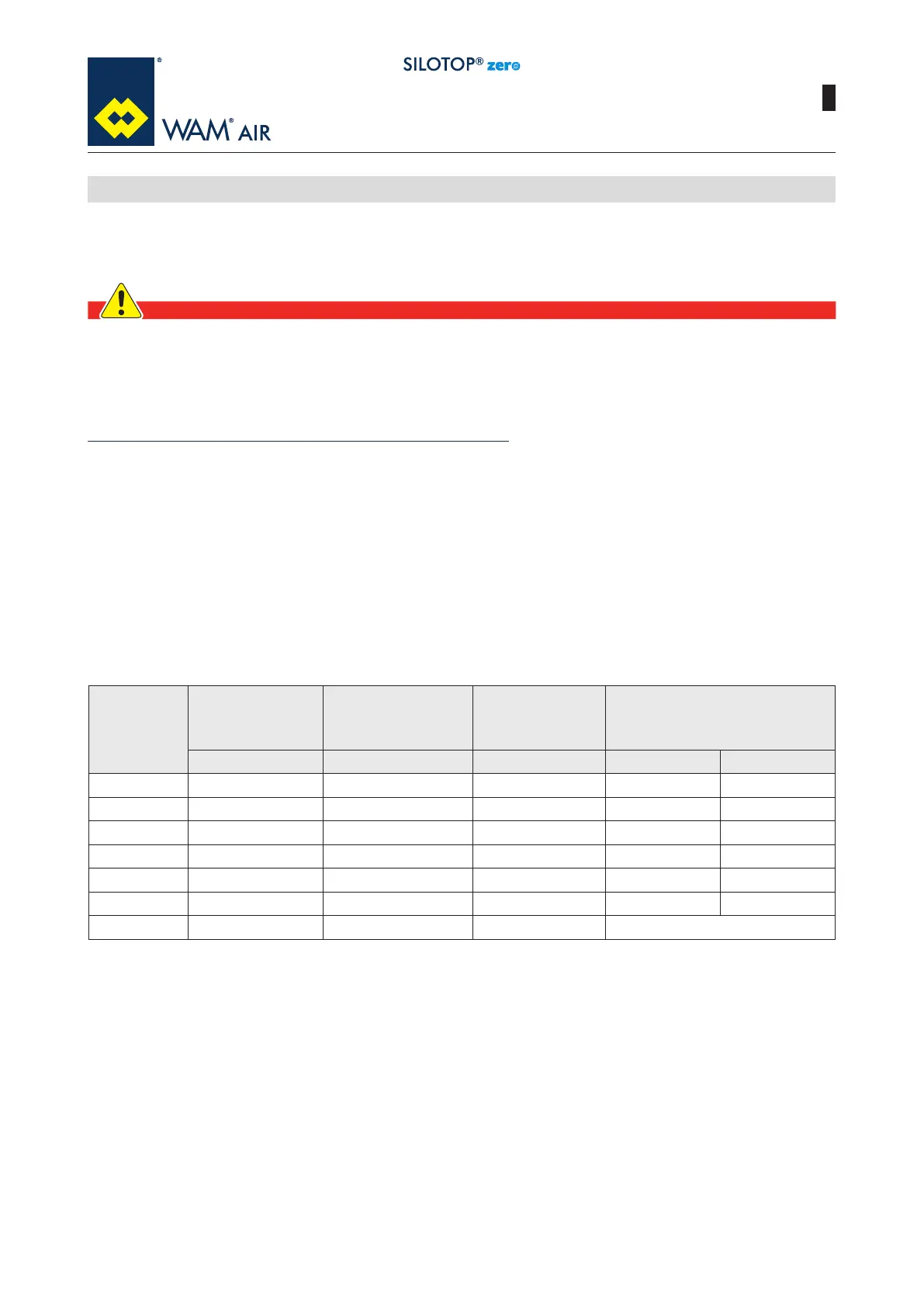
The required air quality must be equal to or over class 4 according to ISO 8573-1.
5.5 Pneumatic connection
Class
Maximum oil
concentration
Maximum
particle
size *
Maximum
concentration **
Maximum
condensation
point under pressure
(mg/m
3
) [µm] (mg/m
3
) °C °F
1 0.01 0.1 0.1 -70 -94
2 0.1 1 1 -40 -40
3 1 5 5 -20 -4
4 5 15 8 3 37.4
5 25 40 10 7 44.6
6 -- -- -- 10 50
7 -- -- -- Not Specied
* The particle size depends on the ltration ratio ßµ = 20.
** At 1 bar (14.5 psia), 20°C (65°F) and a relative vapour pressure of 0.6 (60%).