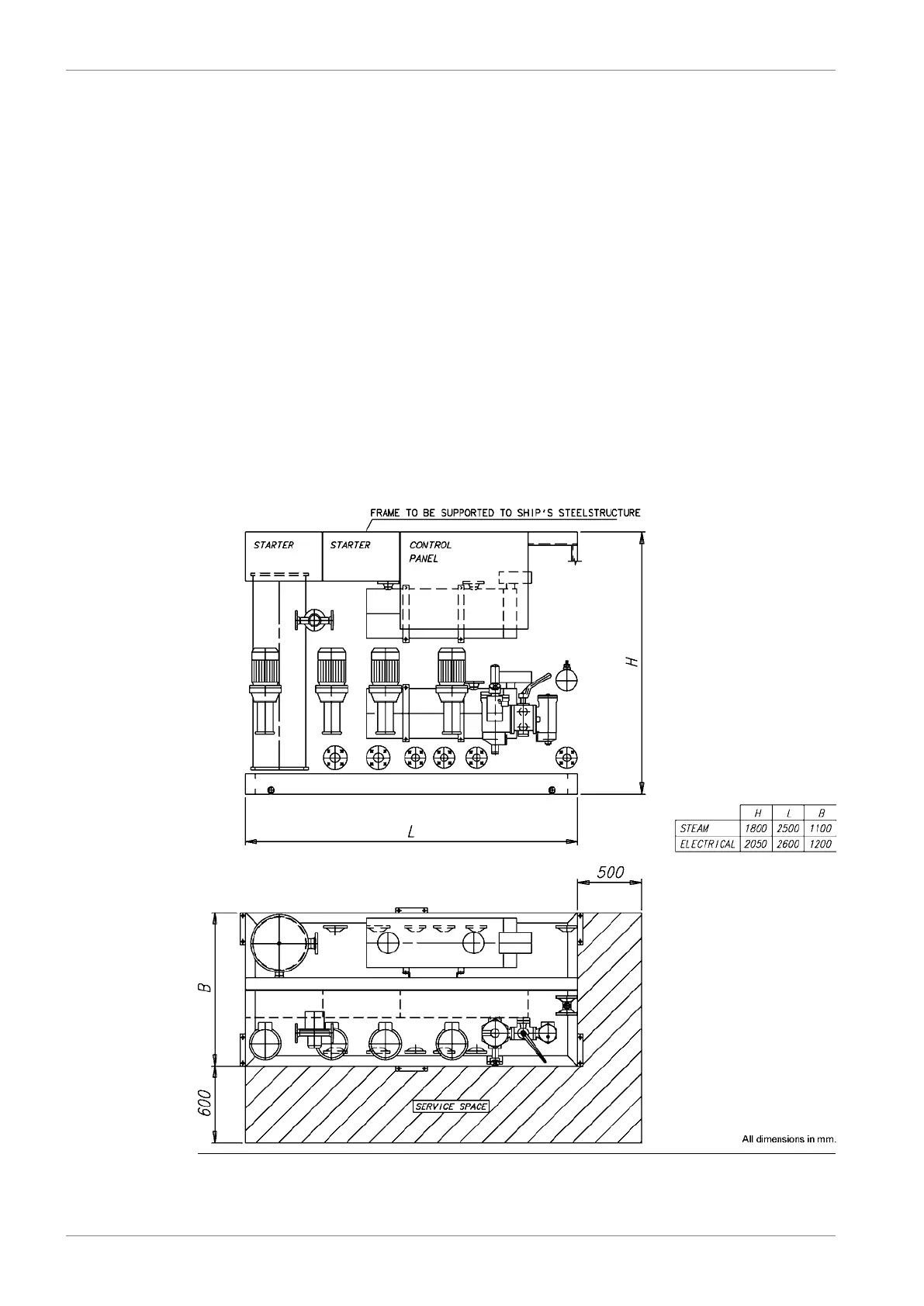
● Two suction strainers
● Two fuel feed pumps of screw type, equipped with built-on safety valves and electric motors
● One pressure control/overflow valve
● One pressurized de-aeration tank, equipped with a level switch operated vent valve
● Two circulating pumps, same type as the fuel feed pumps
● Two heaters, steam, electric or thermal oil (one heater in operation, the other as spare)
● One automatic back-flushing filter with by-pass filter
● One viscosimeter for control of the heaters
● One control valve for steam or thermal oil heaters, a control cabinet for electric heaters
● One temperature sensor for emergency control of the heaters
● One control cabinet including starters for pumps
● One alarm panel
The above equipment is built on a steel frame, which can be welded or bolted to its foundation
in the ship. The unit has all internal wiring and piping fully assembled. All HFO pipes are
insulated and provided with trace heating.
Fig 6-20 Feeder/booster unit, example (DAAE006659)
6-42 DBAD209883
Wärtsilä 46DF Product Guide6. Fuel System