6.3 Fuel gas system
6.3.1 Internal fuel gas system
On the engine, the gas is supplied through common main gas pipes, double wall, running
along the engine, continuing with individual feed pipes to each main gas admission valve
located on the cylinder head. At the gas outlet end there is a gas vent system including the
MCC de-gassing valve (formerly called “venting valve”) which releases the gas pressure.
The gas pressure is controlled on the external Gas Valve Unit (GVU), by the engine control
system based on the engine load. The gas goes through the gas manifold which feeds the
main Gas Admission Valves. The gas is mixed with the intake air immediately upstream of the
inlet valve in the cylinder head. Combustion is initiated by a small amount of pilot fuel oil
injected into the cylinder (pilot fuel), through the smaller nozzle of the injection valve.
A safety filter is placed before every gas admission valve, preventing particles from entering
the valve, with a filtration degree of 80 microns nominal.
Double-wall pipes are used. The gas flows to the cylinders through inner pipes, and the annular
space between the walls is ventilated.
Venting of internal of gas pipes let residual gas fuel dissipate at engine stop, at tripping from
gas to diesel, and in some other situations. The on-engine MCC De-gassing valve releases
the gas pressure from the on-engine pipe and from the external branch between engine and
external GVU gas pressure control valve, to a safe external place. Its other function occurs at
gas mode activation: it shortly opens to let the gas fill the gas pipes.
Ventilation of annular space between the walls is made artificially by underpressure with
flushing air. External ventilation fans installed close to GVU unit brings directly any gas leakage
occurred into the annular space to the gas detectors. Gas detectors sense abnormal presence
of gas particles leaked in the intermediate wall of the pipe, and are installed close to the
external ventilation fans, one per each GVU.
Gas detectors sense abnormal presence of gas particles leaked in the intermediate wall of
the pipe, and are installed close to the external ventilation fans, one per each GVU.
Gas detectors have to be installed in engine room, above engine, to detect gas leakage, due
to a classification societies requirement.
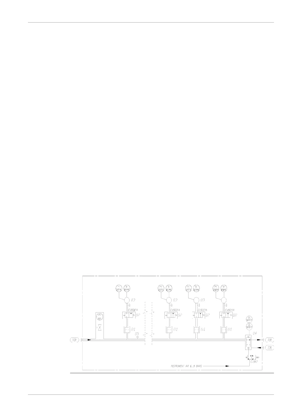
Fig 6-2 Internal fuel gas system, in-line engines (DAAF447413)
DBAD209883 6-11
6. Fuel SystemWärtsilä 46DF Product Guide