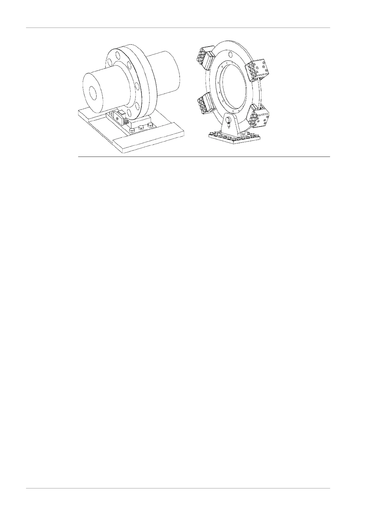
Fig 17-1 Shaft locking device and brake disc with calipers
17.4 Input data for torsional vibration calculations
A torsional vibration calculation is made for each installation. For this purpose exact data of
all components included in the shaft system are required. See list below.
Installation
● Classification
● Ice class
● Operating modes
Reduction gear
A mass elastic diagram showing:
● All clutching possibilities
● Sense of rotation of all shafts
● Dimensions of all shafts
● Mass moment of inertia of all rotating parts including shafts and flanges
● Torsional stiffness of shafts between rotating masses
● Material of shafts including tensile strength and modulus of rigidity
● Gear ratios
● Drawing number of the diagram
Propeller and shafting
A mass-elastic diagram or propeller shaft drawing showing:
● Mass moment of inertia of all rotating parts including the rotating part of the OD-box, SKF
couplings and rotating parts of the bearings
● Mass moment of inertia of the propeller at full/zero pitch in water
● Torsional stiffness or dimensions of the shaft
● Material of the shaft including tensile strength and modulus of rigidity
● Drawing number of the diagram or drawing
Main generator or shaft generator
A mass-elastic diagram or an generator shaft drawing showing:
17-2 DBAD209883
Wärtsilä 46DF Product Guide17. Power Transmission



 To Next Page