8.3 External compressed air system
The design of the starting air system is partly determined by classification regulations. Most
classification societies require that the total capacity is divided into two equally sized starting
air receivers and starting air compressors. The requirements concerning multiple engine
installations can be subject to special consideration by the classification society.
The starting air pipes should always be slightly inclined and equipped with manual or automatic
draining at the lowest points.
Instrument air to safety and control devices must be treated in an air dryer.
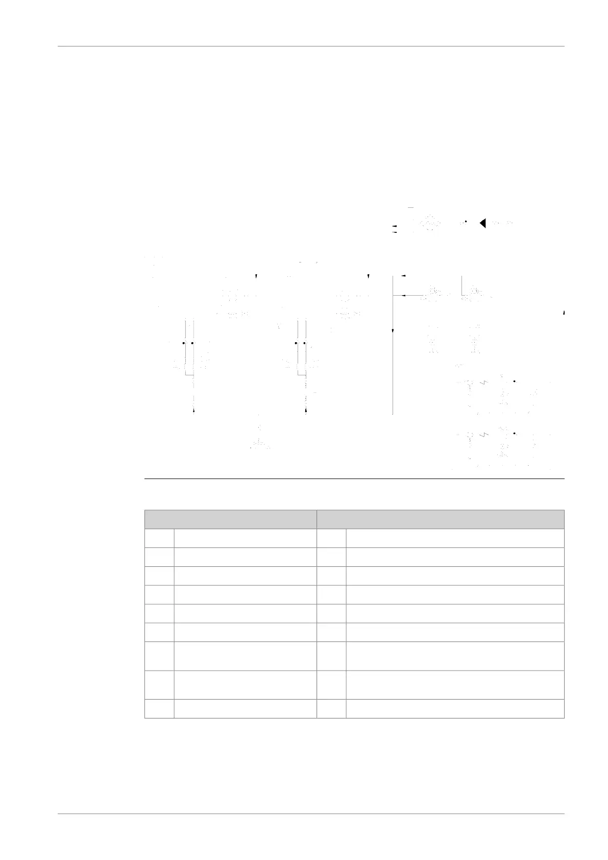
Fig 8-3 Example of external compressed air system (DAAF372066 A)
Pipe connectionsSystem components
Starting air inlet301Diesel engine WV46DF01
Control air inlet302Diesel engine WV46DF02
Driving air to oil mist detector303Flexible pipe connection3H0X
Control air to bypass / wastegate valve311Air filter (starting air inlet)3F02
Starting air compressor unit3N02
Air dryer unit3N06
Compressor (Starting air com-
pressor unit)
3P01
Separator (Stsrting air compressor
unit)
3S01
Starting air vessel3T01
8.3.1 Starting air compressor unit (3N02)
At least two starting air compressors must be installed. It is recommended that the compressors
are capable of filling the starting air vessel from minimum (1.8 MPa) to maximum pressure in
DBAD209883 8-5
8. Compressed Air SystemWärtsilä 46DF Product Guide