Pipe connections
HT-water air vent from exh. valve seat A/B bank424
A/B
HT-water inlet401
LT-water inlet451HT-water outlet402
LT - water outlet452HT-water air vent404
LT- water air vent from CAC A/B bank454
A/B
Water from preheater for HT-circuit406
LT-water from stand by pump457HT-water from stand-by pump408
LT-water air vent A/B bank483
A/B
HT-water drain411
HT-water air vent from air cooler A/B bank416
A/B
9.2.1 Engine driven circulating pumps
The LT and HT cooling water pumps are usually engine driven. In some installations it can
however be desirable to have separate LT/HT pumps, and therefore engines are also available
without built-on LT/HTpumps. Engine driven pumps are located at the free end of the engine.
Connections for stand-by pumps are available with engine driven pumps (option).
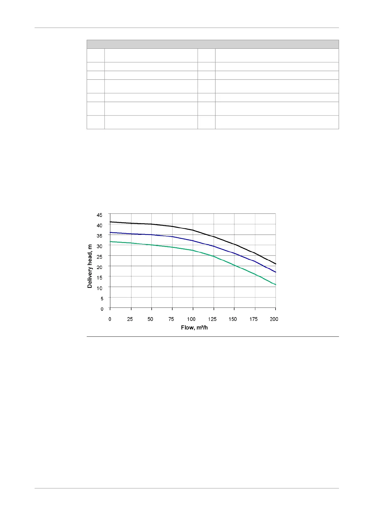
Pump curves for engine driven pumps are shown in the diagram. The nominal pressure and
capacity can be found in the chapter Technical data.
Fig 9-3 L46DF engine driven HT- and LT-pumps
DBAD209883 9-5
9. Cooling Water SystemWärtsilä 46DF Product Guide