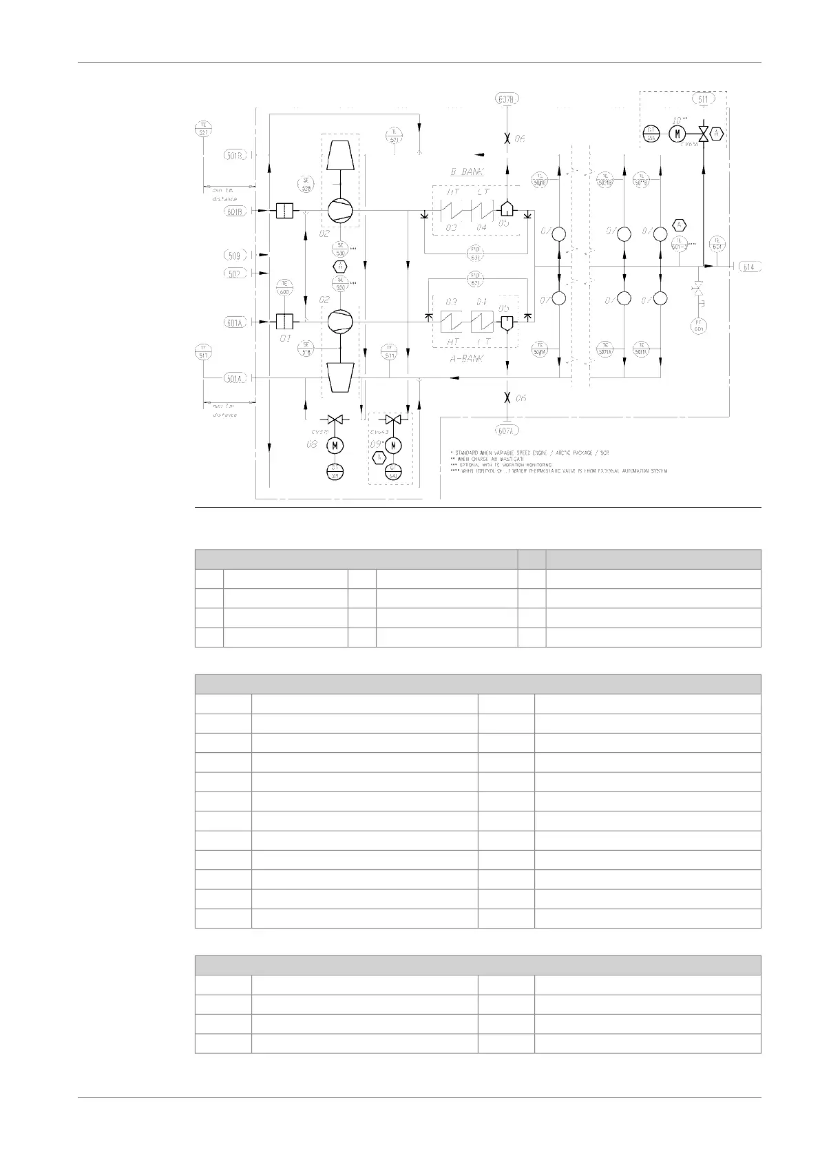
Fig 11-2 Typical Internal charge air/exh gas system, V-engines (DAAF381076A)
System components:
Charge air by-pass valve09*Water mist catcher05Air filter01
Charge air wastegate valve10**Orifice06Turbocharger02
Cylinder head and valves07Charge air cooler (HT)03
Exh. wastegate valve08Charge air cooler (LT)04
Sensors and indicators
Exhaust wastegate controlCV519Exh. gas temperature cyl 0#A/BTE50#1A/B
Exhaust wastegate positionGT519Exh. gas temperature TC A inletTE511
Charge air by pass controlCV643*Exh. gas temperature TC A outletTE517
CAC pressure difference B bankPDI633Exh. gas temperature TC B inletTE521
Charge air by pass positionGT643*Exh. gas temperature TC B outletTE527
Charge air wastegate controlCV656**TC A speedSE518
Charge air wastegate positionGT656**TC B speedSE528
TC A vibrationSE520***Charge air pressure, engine inletPT601
TC B vibrationSE530***Air temperature TC inletTE600
Charge air temp engine inletTE601
Charge air temp engine inletTE601-2****
CAC pressure difference A bankPDI623
Pipe connections
Air inlet to TC A/B bank601 A/BExhaust gas outlet A/B bank501 A/B
Charge air wastegate outlet611**Cleaning water to turbine502
Scavenging air outlet to TC cleaning valve unit614Cleaning water to compressor509
Condensate after air cooler A/B bank607 A/B
DBAD209883 11-3
11. Exhaust Gas SystemWärtsilä 46DF Product Guide
 Loading...