● The combustion in all cylinders is continuously monitored and should it be detected that
all cylinders are not firing reliably, then the engine will automatically trip to diesel mode.
● The exhaust gas system is ventilated by a fan after the engine has stopped, if the engine
was operating in gas mode prior to the stop.
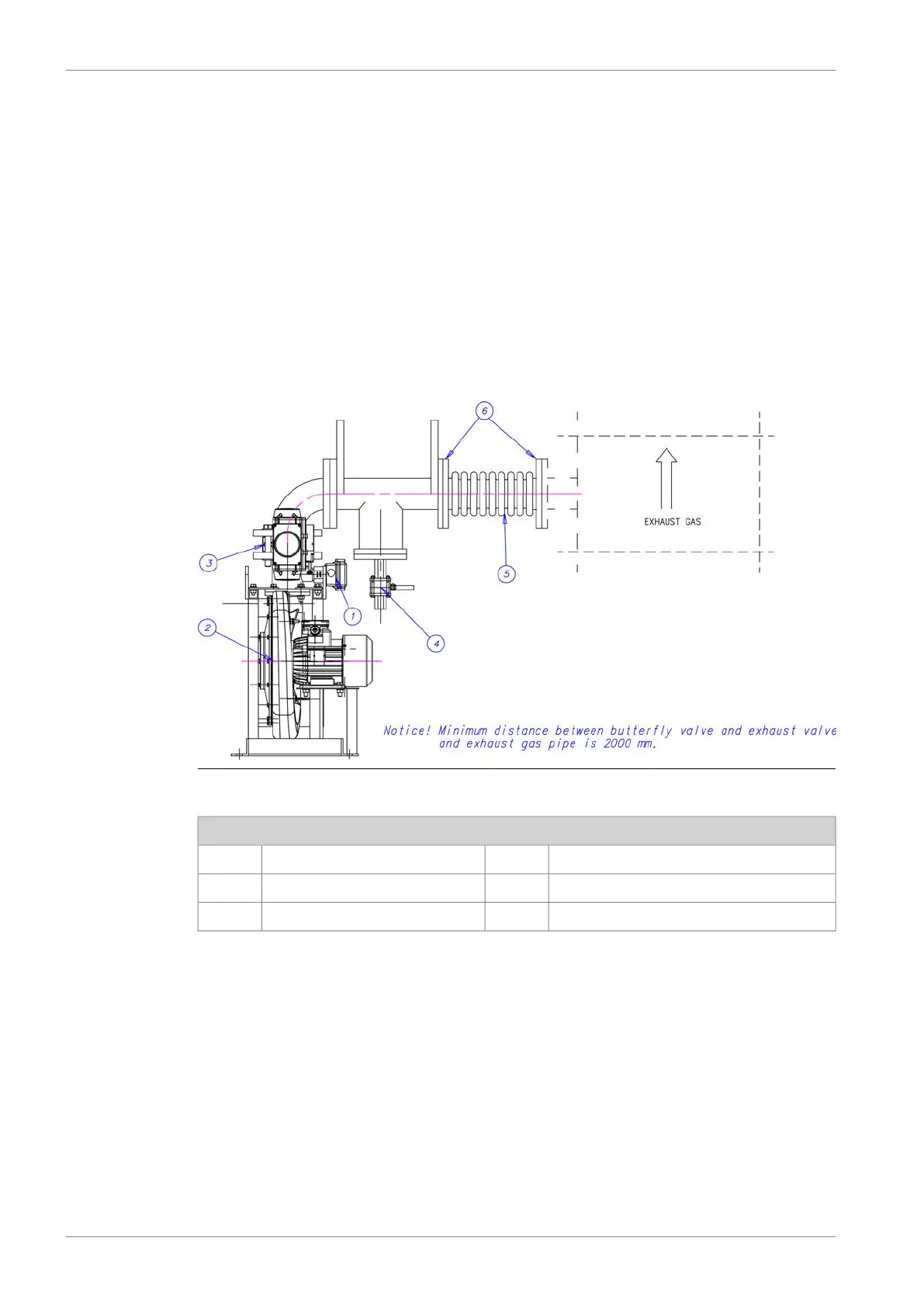
11.3.2 Exhaust gas ventilation unit (5N01)
An exhaust gas ventilation system is required to purge the exhaust piping after the engine has
been stopped in gas mode. The exhaust gas ventilation system is a class requirement. The
ventilation unit is to consist of a centrifugal fan, a flow switch and a butterfly valve with position
feedback. The butterfly valve has to be of gas-tight design and able to withstand the maximum
temperature of the exhaust system at the location of installation.
The fan can be located inside or outside the engine room as close to the turbocharger as
possible. The exhaust gas ventilation sequence is automatically controlled by the GVU.
Fig 11-6 Exhaust gas ventilation arrangement (DAAF315146A)
Unit components
Drain4Switch1
Bellow5Fan2
Flange6Butterfly valve3
11.3.3 Relief devices - rupture discs
Explosion relief devices such as rupture discs are to be installed in the exhaust system. Outlets
are to discharge to a safe place remote from any source of ignition. The number and location
of explosion relief devices shall be such that the pressure rise caused by a possible explosion
cannot cause any damage to the structure of the exhaust system.
This has to be verified with calculation or simulation. Explosion relief devices that are located
indoors must have ducted outlets from the machinery space to a location where the pressure
can be safely released. The ducts shall be at least the same size as the rupture disc. The ducts
shall be as straight as possible to minimize the back-pressure in case of an explosion.
11-6 DBAD209883
Wärtsilä 46DF Product Guide11. Exhaust Gas System